Figures & data
Figure 1 DTEM is implanted in the CF-100TL Colonoscope with the Main Parts of the DTEM Shown.
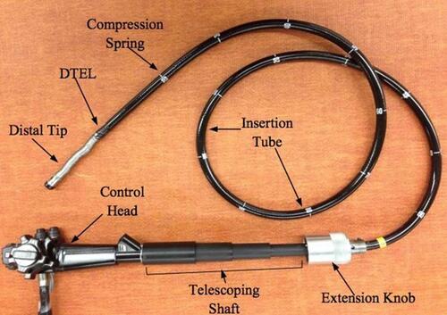
Figure 2 The compression spring of the DTEM attached to the metal adapter.
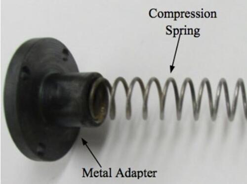
Figure 3 Components of the extension knob of the DTEM.
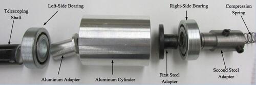
Figure 4 The DTEL which is a 60 cm compression spring.
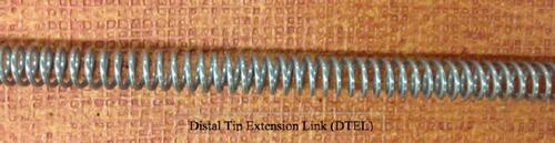
Figure 5 The telescoping shaft of the DTEM: illustrates the telescoping shaft when fully extended.
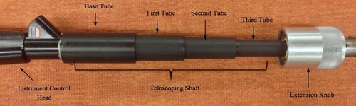
Figure 6 The colonoscope holder holds the prototype during performing the extension experiments.
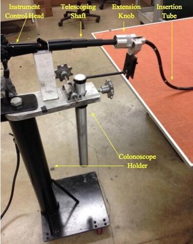
Figure 7 Some of the layouts that come with the CTM. The N shape, Alpha shape, and Reverse Alpha shape are shown because they present the most common looping shapes.
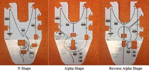
Figure 8 Illustration of the five configurations used in the extension test.
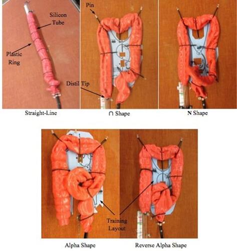
Figure 9 The force sensor attached to the extension knob of the DTEM.
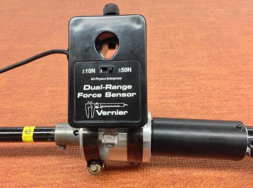
Figure 10 Setup of the bending angle test with illustration of the main components. The bending angle being tested in this figure is 90°.
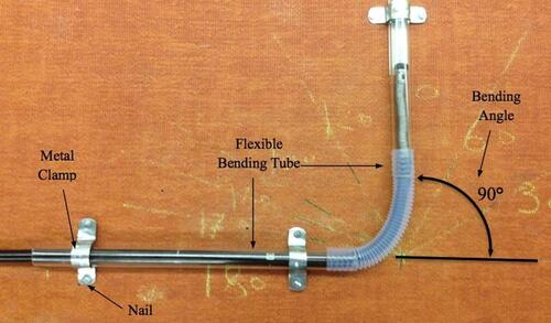
Figure 11 The flexible bending tube consists of two transparent tubes and one corrugated tube. The device is used to bend the insertion tube in different angles.
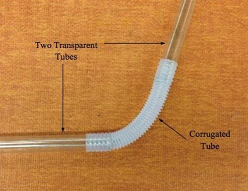
Figure 12 The displacements of the distal tip caused by pushing the three tubes of the telescoping shaft gradually in the telescoping shaft.
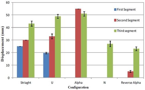
Figure 13 The numbers of turns of the three stages in each configuration.
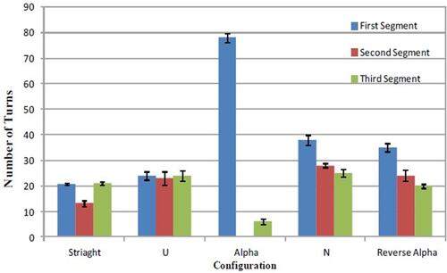
Figure 14 The displacement percentage caused by both compressing the telescoping shaft and rotating the extension knob.
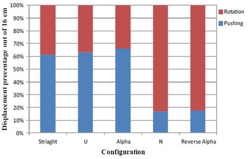
Table 1 The Success Rates of the DTEM to Extend the Distal Tip 16cm
Figure 15 The insertion tube of the colonoscope consists of three layers: Polymer resin, mesh tube, and metal flex tube.Citation22
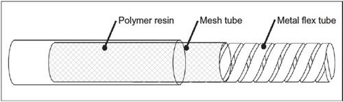
Table 2 Maximum Torque Applied During the Extension of the Distal Tip in Each Configuration
Figure 16 Torque needed to rotate the extension knob and displace the distal tip in each stage of the extension process in all studied configurations.
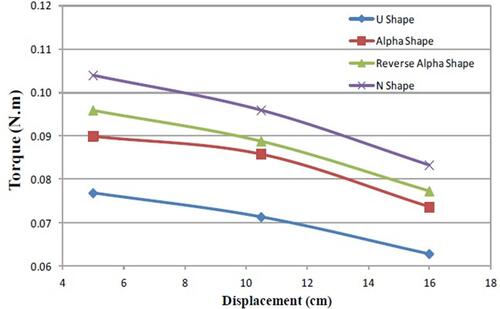
Figure 17 The average torque applied to rotate the extension knob to reach full extension for the distal tip in the configurations.
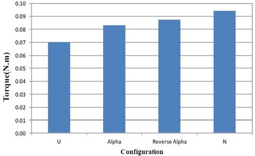
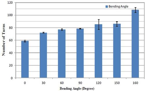
Figure 18 Bending Angles and number of turns obtained from testing the insertion.