
Figures & data
Table 1 General Characteristics of the Study Population
Figure 1 (A) Representative figure of the industrial design drawings of DYNAtraq device. The intention of taking the DYNAtraq device to the molding, injection, clinical validation and future commercialization process has required all the necessary plans being designed in accordance with current regulations. These design drawings were also necessary to file the patent application. For more details on the respective plans, please contact the principal investigator. (B) Three-dimensional space graphic design of DYNAtraq device.
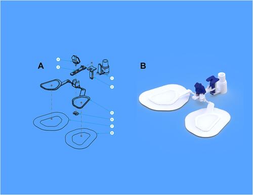
Figure 2 Specialized 3D graphic design of the end of the DYNAtraq device. (A) Frontal plane view; (B and C) obliquus plane view; (D) sagittal plane view; (E) axial plane view.
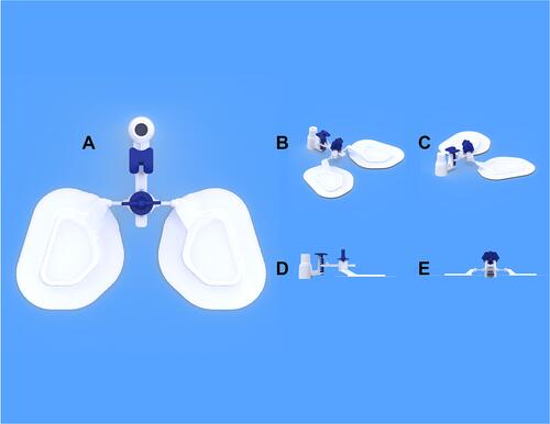
Figure 3 Conceptual model of DYNAtraq device evaluated in life-size human manikins. (A) Frontal plane view; (B) and (C) oblicuous plane view.
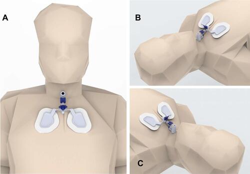
Figure 4 Cytotoxicity tests. The cytotoxicity test was carried out following the international standard ISO 10993–5. The extraction process was carried out according to ISO 10993–12. Different concentrations of the extract (100%, 75%, 50%, 25% and 12.5%) were exposed to the L929 cell line for 24 hours. Bars represent mean (SD) of the viability obtained in triplicate experiments.
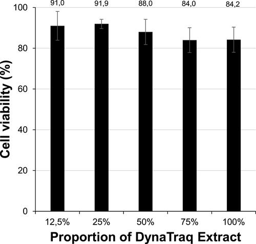
Figure 5 Tensile loads tolerated by the connectors before disconnection from the tracheostomy tube. Under experimental laboratory conditions, high values (several KgF) were recorded for both the DYNAtraq 15mm connector and the reference connector before they were disconnected from the tracheostomy tube. Bars represent the mean (SD) value of the studies performed in triplicate for both connectors.
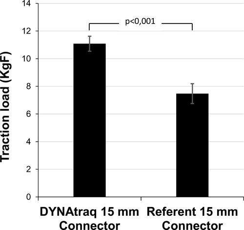
Figure 6 Comparisons Between Sequential Photographs Taken Prior To And After The Placement Of The DYNAtraq Device In Ventilated Patients. Sequential pictures from three selected patients to show cephalo-caudal view of intrasubject comparisons prior to and after the placement of the DYNAtraq device. Pictures (A, C and E) represent the referent caudal-cephalic photographs patients without the device, whereas pictures (B, D and F) show caudal-cephalic photographs of the same patient once the device has been placed on the chest taking the midline of the sternum for reference. Color code: (Yellow arrows): axis of the tracheostomy tube alignment at baseline (without the device) position; (Red arrows): axis of the tracheostomy tubes using the DYNAtraq device. It is also shown in (E and F) pictures the degree of lateral misalignment in a patient in the face of equivalent left to right push loading on the tracheostomy tube. Note that the device offers greater tolerance to the pushing load as it is deduced from a lower angular displacement despite of an equivalent external load.
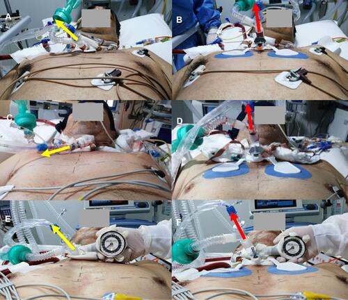
Figure 7 Patient With DYNAtraq Dispositive: Lateral View In Supine Position Comparisons Between Sequential Photographs Taken Prior To And After The Placement Of The DYNAtraq Device In Ventilated PatientS. Sequential pictures from three selected patients to show latero-lateral view of intrasubject comparisons prior to and after the placement of the DYNAtraq device. Pictures (A, C and E) represent the referent latero-lateral photograph of the patients without the device, whereas pictures (B, D and F) show latero-lateral photographs of the same patient once the device has been placed on the chest following the interclavicular line reference. Color code: (Yellow arrows): axis of the tracheostomy tube alignment at baseline (without the device) position; (Red arrows): axis of the tracheostomy tubes using the DYNAtraq device.
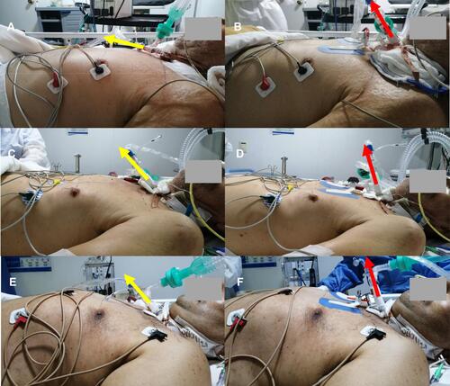
Table 2 Perception of Use of the DYNAtraq Device in Health Workers of the ICU