Figures & data

Figure 1 Main view of non-invasive oxygen-positive pressure helmet conceptions.
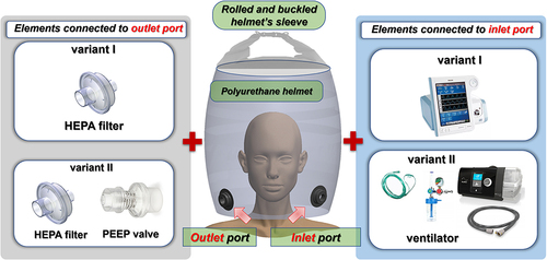
Figure 2 Main view of the designed helmet: (a) left-hand view, (b) frontal view, (c) right-hand view.
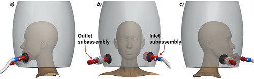
Figure 3 The view of the inlet port with particular parts.
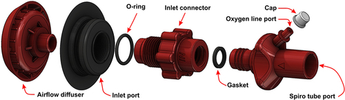
Figure 4 Cross-sectional view of the inlet subassembly elements.
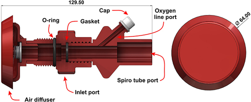
Figure 5 The view of the outlet port with particular parts.
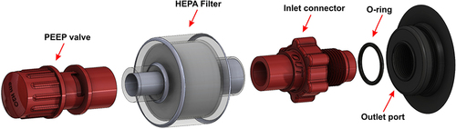
Figure 6 Cross-sectional view of the outlet subassembly elements.
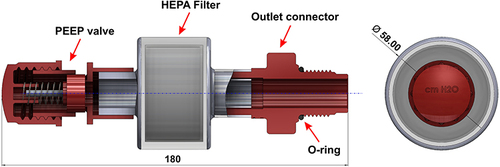
Table 1 PET-G 3D Printing Parameters Recommended by the Devil Design Filament Producer
Figure 7 Geometry of samples used in roughness measurements.
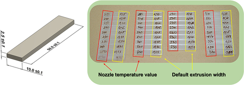
Table 2 Results of Ra Roughness Measurements of 3D Printed PET-G Material Samples with Different Nozzle Temperature and Default Extrusion Width Values
Table 3 Results of Rz Roughness Measurements of 3D Printed PET-G Material Samples with Different Nozzle Temperature and Default Extrusion Width Values
Figure 8 Results of the toughness tests of PET-G specimens manufactured with the use of different 3D printing parameters.
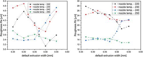
Figure 9 The main view of the ASTM E466:96 tensile test specimen (a) Shape and dimensions, (b) Orientation of manufacturing (c) Real specimens used in tests.
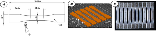
Figure 10 The main view of laboratory stands used for marking and geometric quality control of dog bone specimens: (a) FIBER ATMS 2020 PRO laser marker, (b) Baty Venture XT optical measurement machine.
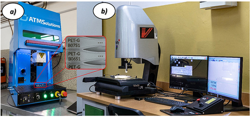
Figure 11 The main view of the laboratory stand used to perform the tensile tests of PET-G material.
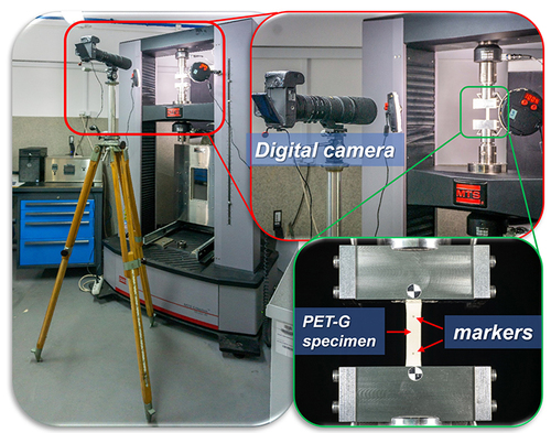
Table 4 The Mechanical Properties of PET-G are Estimated on the Basis of the Results of the Tensile Tests
Figure 12 The average stress–strain curve with standard deviation determined on the basis of the results of the tensile tests.
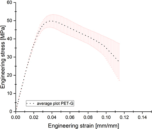
Figure 13 The scheme of preparation of the G-code file in the Prusa Slicer software: (a) The geometry of particular elements exported to *.stl format, (b) Import to Prusa Slicer and definition of elements orientation on the working table, (c) Visualization of particular types of 3D printing features: - solid (Orange colour), infill (yellow colour), support structure (green colour).
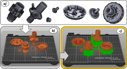
Figure 14 The main view of the manufacturing process of the fitting elements (a) during the 3D printing process, (b) the final result.
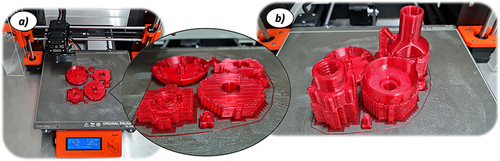
Figure 15 The main view of 3D printed fitting elements (a) before, (b) after removing support structures.
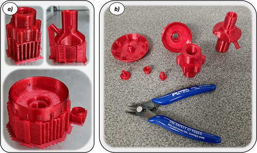
Figure 16 The main view of the inlet and outlet fitting elements mounted in the helmet ports.
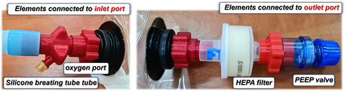
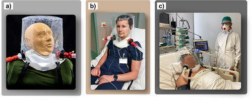
Figure 17 Variants of preliminary tests of developed helmet equipped with 3D printed fitting elements: (a) tests with the phantom model, (b) tests with student volunteers, (c) Preliminary clinical tests with patients.