Figures & data
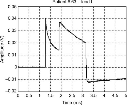
Figure 1 Schematic of the wideband biopotential amplifier.
Abbreviations: ECG, electrocardiography; RL, right leg; Rp, protection resistors (1.1 kΩ); Rg, instrumentation amplifier gain resistor (180 kΩ); C1 =4.7 mF, R1 =3.3 MΩ, passive high-pass filter; C2 =10 nF, R2 =100 kΩ, active low-pass filter; R3, active filter gain resistor (1 kΩ).
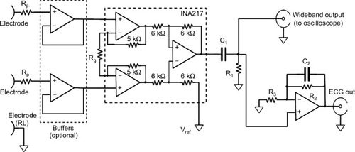
Figure 2 Lead I and lead II pacemaker waveform and the corresponding vectorcardiogram
Notes: (A) An example of monopolar pacemaker waveforms recorded from ECG lead I (upper trace) and from ECG lead II (lower trace). (B) Frontal plane vectorcardiogram of the pacemaker pulse.
Abbreviation: ECG, electrocardiography.
Abbreviation: ECG, electrocardiography.
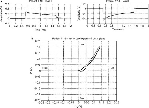
Figure 3 An example of a monopolar pacemaker waveform recorded from ECG lead I.
Abbreviation: ECG, electrocardiography.
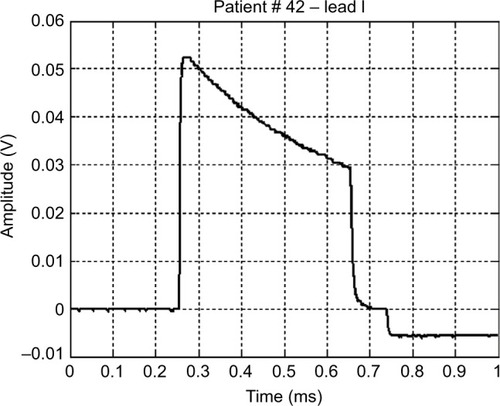
Figure 4 An example of a bipolar pacemaker waveform recorded from ECG lead I.
Abbreviation: ECG, electrocardiography.
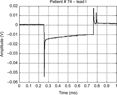
Figure 5 Waveform of a monopolar pacemaker with a defective output circuit.
Note: The image shows the abrupt disruption of the proper exponential decay signal.