Figures & data
Figure 1 Chemical structures of caffeic acid (A) and mitochondriotropic antioxidant AntiOxCIN3 (B).
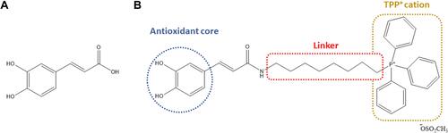
Figure 2 (A) Fluorescence spectra of HSA (2.0×10⁻⁶ M) in the presence of increasing AntiOxCIN3 concentrations (0 to 3.5×10⁻⁴ M) at 37 °C. (B) Deconvolution of HSA Trp (long dashes) and Tyr (short dashes) residues emission bands in the absence (pink) and in the presence (blue) of 3.5×10⁻⁴ M of AntiOxCIN3. (C) Synchronous fluorescence spectra of HSA (2.0×10⁻² M) in absence and in presence of increasing concentrations of Anti-OxCIN3 (0 to 3.50×10⁻⁴ M) with Δλ = 15 nm corresponding to Tyr residues and (D) Δλ = 60 nm corresponding to Trp residues.
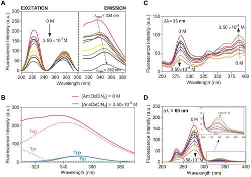
Figure 3 Graphic representation of Rh obtained from DLS (A) and Zeta Potential values (B) for HSA and HSA-AntiOxCIN3 ([AntiOxCIN3] from 0 to 3.50×10⁻⁴ M), at three different temperatures represented by different colors and signs. The black dashed line shows the tendency for neutralization upon AntiOxCIN3 addition observed by increase values of Rh and zeta potential.
![Figure 3 Graphic representation of Rh obtained from DLS (A) and Zeta Potential values (B) for HSA and HSA-AntiOxCIN3 ([AntiOxCIN3] from 0 to 3.50×10⁻⁴ M), at three different temperatures represented by different colors and signs. The black dashed line shows the tendency for neutralization upon AntiOxCIN3 addition observed by increase values of Rh and zeta potential.](/cms/asset/8e762b98-5a41-4dba-bc69-c0ddb0349ab4/dnsa_a_12173929_f0003_c.jpg)
Figure 4 PC membrane model system partition coefficient of AntiOxCIN3 by derivative spectrophotometry: (A) Third derivative of AntiOxCIN3 (2.0×10⁻⁴ M) absorption spectra in aqueous buffered phase pH=7.4 (red), after incubation with PC membrane model system (0–3.0×10⁻³ M) (black) and PC membrane model system in the absence of AntiOxCIN3 (grey); (B) Non-linear fitting by EquationEquation 1(1) of derivative absorbance at λ=341 nm as a function of PC membrane model system concentration. (C) Third derivative of the absorbance spectra and respective non-linear fitting by EquationEquation 1
(1) (dashed line) at several temperatures; (D) van’t Hoff plot representing the Gibbs free energy values as function of the inverse of temperature, in K−1, with the transition temperature between gel (Lβ’) and fluid (Lα) lipid phases highlighted.
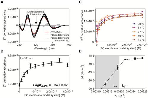
Figure 5 (A) Stern-Volmer plots of the probes n-AS incorporated in the PC membrane system at 37 °C as a function of AntiOxCIN3 ([AntiOxCIN3]M). Different colors and signs represent the different probes used. The full line represents the linear fitting applied to steady-state data. The dashed line represents the linear fitting applied to the data obtained from lifetime measurements. (B) Schematic representation of the possible location of the n-AS (n=3, 6, 9 and 12) fluorescent probes and AntiOxCIN3 within PC molecules of the PC membrane system. Membrane microviscosity assessment studies in the presence (red) and absence (black) of AntiOxCIN3 and respective sigmoidal fits: (C) Anisotropy, rss, profile of DPH probe in the PC membrane model system dependent on the temperature with fitting using EquationEquation 3(3) ; (D) Sigmoidal profile of normalized mean count rate (MCR) obtained by DLS as function of temperature with sigmoidal fit using EquationEquation 14
(14) .
![Figure 5 (A) Stern-Volmer plots of the probes n-AS incorporated in the PC membrane system at 37 °C as a function of AntiOxCIN3 ([AntiOxCIN3]M). Different colors and signs represent the different probes used. The full line represents the linear fitting applied to steady-state data. The dashed line represents the linear fitting applied to the data obtained from lifetime measurements. (B) Schematic representation of the possible location of the n-AS (n=3, 6, 9 and 12) fluorescent probes and AntiOxCIN3 within PC molecules of the PC membrane system. Membrane microviscosity assessment studies in the presence (red) and absence (black) of AntiOxCIN3 and respective sigmoidal fits: (C) Anisotropy, rss, profile of DPH probe in the PC membrane model system dependent on the temperature with fitting using EquationEquation 3(3) ; (D) Sigmoidal profile of normalized mean count rate (MCR) obtained by DLS as function of temperature with sigmoidal fit using EquationEquation 14(14) .](/cms/asset/1b885197-f153-45e5-a4a1-b8e3af7c832d/dnsa_a_12173929_f0005_c.jpg)
Table 1 Fluorescence Quenching Constants Obtained from Measurements of Fluorescence Quenching Studies for n-AS Fluorescence Probes in PC Membrane Model System at 37°C
Figure 6 WAXS patterns of PC membrane system in the absence (A) and presence (B) of AntiOxCIN3 with some temperatures highlighted in red.
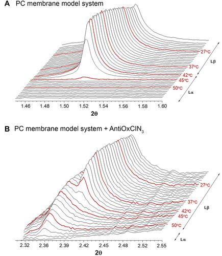
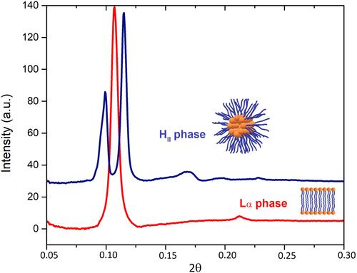
Figure 7 SAXS patterns of a BPL membrane model system in the presence of AntiOxCIN3 before (red line) and after (blue line) the transition between lamellar phase (Lα) to inverted hexagonal phase (HII).