
Figures & data
Table 1 Absolute and relative contraindications for SMILE
Table 2 Laser parameters set during SMILE in various treatment modes
Table 3 Cap and lenticule treatment parameters for small incision lenticule extraction using VisuMax femtosecond laser system
Figure 1 Femtosecond laser application in small incision lenticule extraction.
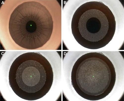
Figure 2 Two concentric rings visible after femtosecond laser application, with the outer ring signifying the cap cut (red arrow) and the inner ring signifying the lenticule cut (yellow arrow).
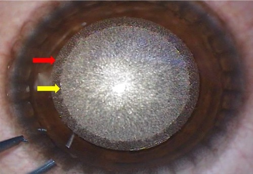
Figure 3 Lenticule dissection and extraction.
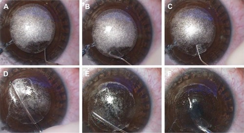
Table 4 Intraoperative complications observed during small incision lenticule extraction
Figure 4 Opaque bubble layer.
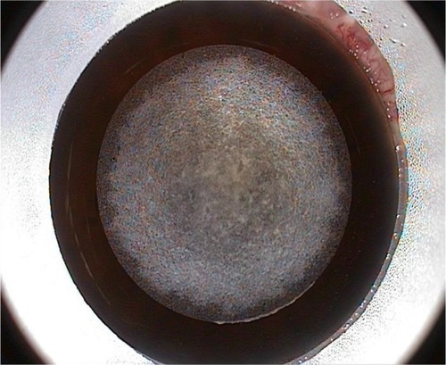
Figure 5 Black spots.
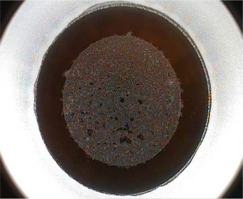
Figure 6 Suction loss during lenticule cut.
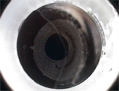
Table 5 Management of intraoperative suction loss based on the stage of suction loss
Figure 7 Cap lenticular adhesion with a completely retained lenticule as seen on the anterior segment optical coherence tomography.
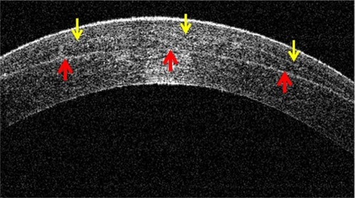
Table 6 Intraoperative signs to prevent and identify cap lenticular adhesions
Figure 8 Meniscus sign (yellow arrow).
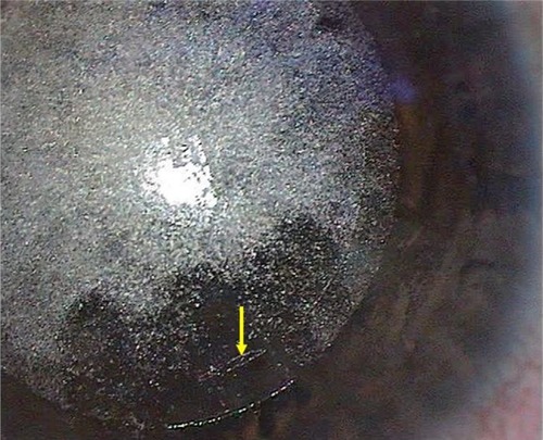
Figure 9 Side-cut tear due to forceful lenticule extraction.
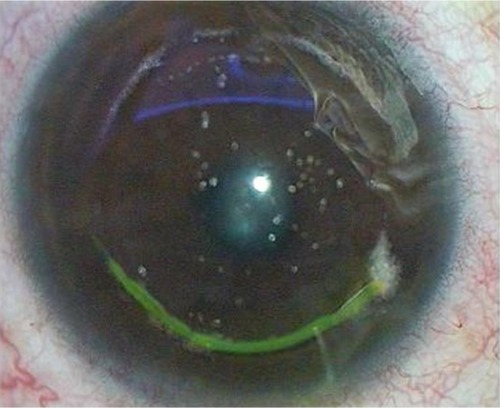
Table 7 Modifications of surgical technique of small incision lenticule extraction