Figures & data
Figure 1 (A) Schematic drawing of the newly designed needle (NDN): 1 – side port with smooth edges for drug delivery; 2 – absence of the dead space; 3 – beveled tip with angle 18º; 4 – caliber 30 gauge. (B) Enlarged view of the NDN prototype. (Created by L. Lytvynchuk.)
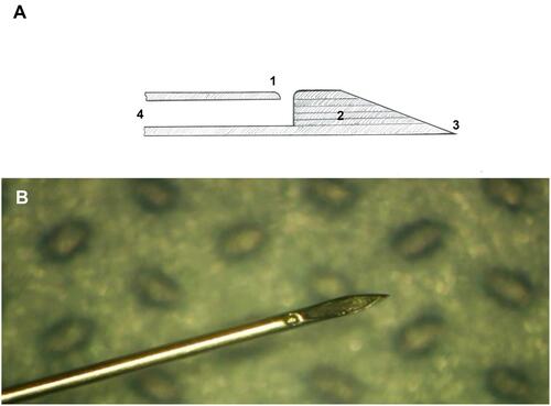
Figure 2 Overview of the two needle types used in the experimental study. Enlarged view of the standard hypodermic needle (SHN) 30 G (A–C) and the newly designed needle (NDN) 30 G (D–I). Yellow arrow indicates the presence of a front tip orifice in the SHN (A). iOCT of the SHN 30 G needle (B) and NDN 30 G needle (E and H). (B) Yellow arrow indicates the sharp inner edge of the tip of the SHN. Yellow arrows indicate absence of the tip orifice (D and E) and the side port (G and H). (C and F) Schematic view of the cellular content (red arrows) captured by the SHN 30 G and NDN 30 G needles, respectively. (I) The direction of the injection stream of the NDN (red arrow). (Created by L. Lytvynchuk.)
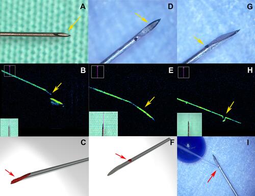
Figure 3 Enlarged view of the NDN tip after being inserted into the vitreous cavity of the cadaver pig eye (imaging performed with an E4 Ophthalmic Endoscopy System Endo Optiks®). Light reflection depicts closed front opening (white arrow). Red arrow indicates side port of the NDN. (Created by L. Lytvynchuk.)
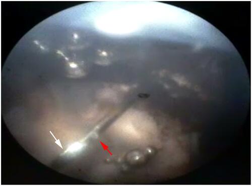
Table 1 Comparison of the Number of Cells Revealed in the Needle Tip Aspirates After IVIs Were Performed on Rat Eyes, Including Conjunctival Epithelial Cells, Ciliary Body Epithelial Cells and Granulated Basophilic Protein Sediments
Figure 4 Cells revealed from needle tip aspirates after IVIs were performed on rat eyes. Conjunctival epithelial cells (A), ciliary body epithelial cells (B) and granulated basophilic protein sediments (C) were found in aspirates taken from both needle types (magnification 400×, staining with azure-2–eosin). (Created by L. Lytvynchuk.)
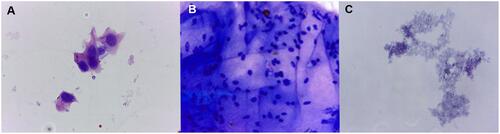
Figure 5 Comparison of the injection stream during IVI with the SHN (A–D) and the NDN (E–H) in cadaver pig eyes. During the initial IVI stage the dye appears on the needle tip of the SHN (B, yellow arrow) and on the side of the NDN needle (F, yellow arrow) while the needle tip remains free of dye (F, red arrow). The dye spreads in conical manner from the SHD (C, red lines) and it spreads around the needle tip of the NDN (G, dashed line). Diffuse filling of the vitreous of the injection site appears to be similar in the case of the SHN and NDN. (Created by L. Lytvynchuk.)
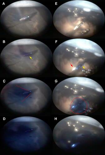
Table 2 Comparison of the Penetration Force Measured for the Injection Performed by the NDN and SHN Types
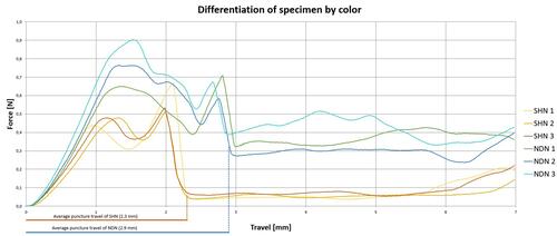
Figure 6 Penetration resistance of the NDN and SHN measured and plotted as a load-displacement diagram. Each needle type was tested three times: yellow, orange and red lines – for the SHN; green, blue and turquoise lines – for the NDN. Ddashed lines indicate an average puncture travel of the needle tips: red dashed line for the SHN (2.3mm), blue dashed line for the NDN (2.9mm). (Created by J. Hiemstra.)