Figures & data
Figure 1 SOR–ICP line as an anatomical limitation. The line formed by the SOR–ICP is the anatomical limit where the tip of a straight probe can reach most anteriorly after entering the LS through the ICP. The red arrow indicates when the LS and NLD inclined anteriorly to the line formed by the SOR–ICP. Manipulating straight probes poses a risk for forming an iatrogenic false passage posterior to the original lacrimal duct.
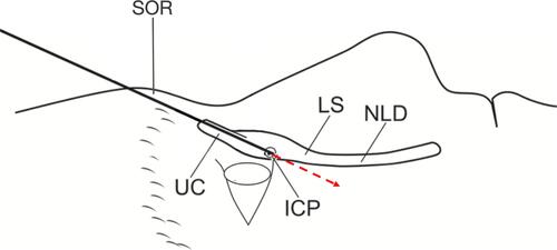
Figure 2 SOR interference during manipulation of the dacryoendoscope. SOR interferes the manipulation of the endoscope. It is difficult to tilt the probe horizontally than the SOR. However, the endoscope can stand more vertically than the SOR.
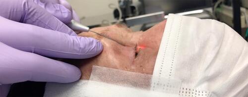
Figure 3 CBCT-DCG sagittal image sectioning the lacrimal duct. The figure shows a dacryocystographic image of the nasolacrimal duct on the right side from a patient diagnosed with left-sided unilateral primary acquired nasolacrimal duct obstruction. The original image was converted to monochrome to facilitate observation of the contrast media.
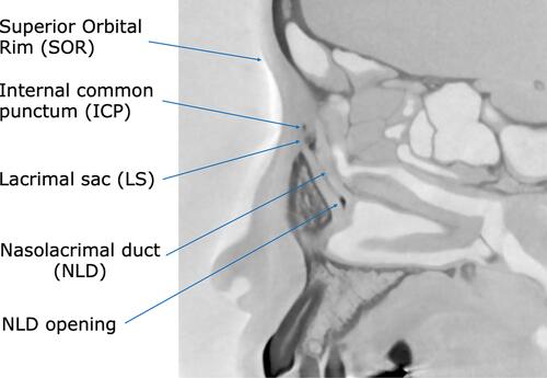
Figure 4 Parameters measured in CBCT-DCG images. (A) Angle formed by SOR–ICP–NLD opening. In this case, the line connecting the ICP–NLD opening was inclined anteriorly at 4 relative to the line connecting the SOR–ICP. (B) Angle formed by LS and NLD. In this case, the long axis of the NLD was inclined posteriorly at 10° relative to the LS. (C) Length of LS and NLD, with 6.15 mm and 14.30 mm, respectively.
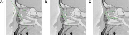
Table 1 Lacrimal Duct Parameters Measured on Sagittal Sections of CBCT-DCG Images
Figure 5 Example of a large SOR–ICP–NLD opening angle. On the left side is the original image. On the right side, a relatively large angle of 24° is seen, which is due to the elevation of the SOR and the anterior inclination of the NLD.
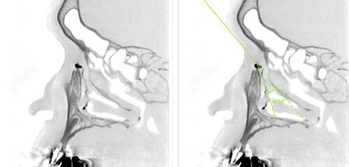
Figure 6 Test results for the normal distribution of the measured parameters. (A) SOR–ICP–NLD opening angle: The average angle was 10.7° ± 7.4° (range, −6° to +27°) and followed a normal distribution (p = 0.55). (B) LS–NLD angle: The mean angle was −6.84° ± 13.7° (range, −43° to +34°) and followed a normal distribution (p = 0.28). (C) LS length: The mean length was 8.9 ± 2.2 mm (range, 5.4–17.1) and did not follow a normal distribution (p = 0.078). (D) NLD length: The mean length was 13.3 ± 2.7 mm (range, 5.7–20.7) and followed a normal distribution (p = 0.17). The p-value was determined by the Shapiro–Wilk test. A p-value of >0.05 indicated a normal distribution.
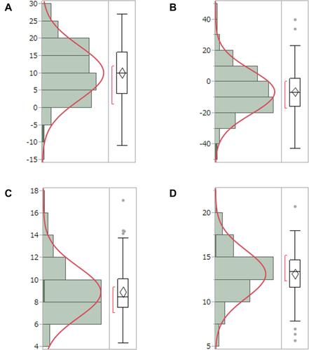
Figure 7 Case in which the NLD is inclined anteriorly to the LS (anterior bending type). On the left is the original image. On the right side, the long axis of the NLD was anteriorly inclined by +14° relative to that of the LS.
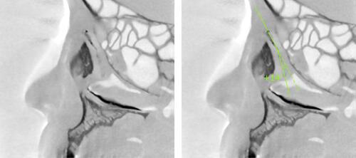
Figure 8 Case in which the NLD is inclined posteriorly to the LS (posterior bending type). On the left is the original image. On the right side, the long axis of the NLD was posteriorly inclined by −21° relative to the LS.
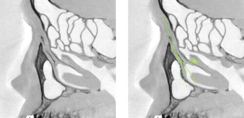
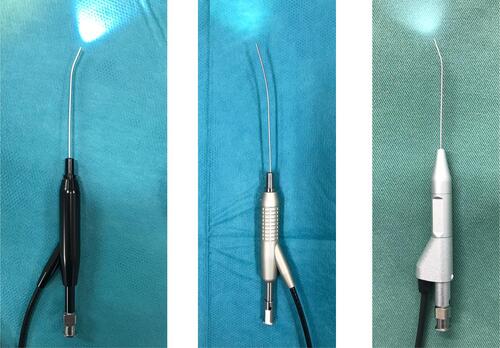
Figure 9 Dacryoendoscope with an anteriorly bent-tip probe and a curve-tipped probe. Left: CK10® (FiberTech Co., Ltd., Tokyo, Japan); external diameter, 0.9mm; field of view, 60°; image quality, 10,000 pixels. Middle: CH15C® (FiberTech Co., Ltd., Tokyo, Japan); external diameter, 0.82 mm; field of view, 70°; image quality, 15,000 pixels. Right: LAC-06-FY® (Machida Endoscope Co., Ltd., Chiba, Japan); external diameter, 0.9 mm; field of view, 65°; image quality, 10,000 pixels.