Figures & data
Figure 1 The inner bore of the Cetus probe (A.R.C. Laser, Erlagen, Germany). The titanium inside edge of the probe is the targeting spot for this nanosecond laser. Pulsing the laser emits a plasma formation, and a focused abrupt ultrasound surge is emitted from this point that extends outwards. The probe serves as the aspiration port as well, thus engaging the cataract fragments. The outer silicone sleeve in the coaxial version of the probe used provides the irrigation.
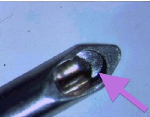
Figure 2 The LenSx® (Alcon, Fort Worth, TX, USA) femtosecond laser capsulorhexis, lens fragmentation, and cornea incision final plan. The capsulorhexis planned is shown by the purple arrows both on the left (coronal) and right (cross-sectional) images of this intraoperative optical coherence tomography planning tool. The lens fragmentation plan is shown by the yellow crosshairs and arrows in the left coronal view. Of note is that the planned lens fragmentation diameter is narrower than the capsulorhexis diameter. On the right view, the lens fragmentation is shown in cross section. Its anterior extent, just under the anterior capsule, is shown by red and magenta arrows. The posterior extent is shown by the blue arrows and is 500 microns short of the posterior capsule.
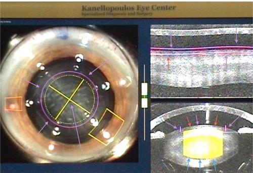
Figure 3 Visco-separation (yellow arrow) of the femto-dissected cataract quadrants. The end of the Viscoat® (Alcon, Fort Worth, TX, USA) irrigation cannula has been inserted in these two cataract quadrants, completing their physical separation. Note the retro-cataract air bubble, which can be seen escaping anteriorly, facilitated by the space created between the visco-separated cataract fragments.
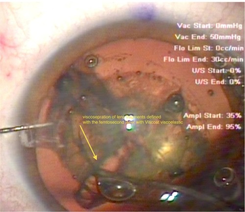
Figure 4 Insertion of the irrigation cannula just under the capsulorhexis at the 6 o’clock position (12 o’clock in this surgeon’s view) – another novel step in the procedure. The surge of the hydrodissection at this point has “pushed” the separated cataract quadrant (yellow oval) into the pupillary plane. Note again, at this stage of the procedure, the multiple bubbles relocating anteriorly, just under the cornea. These bubbles represent gas produced by the lens fragmentation stage of the femtosecond procedure and have been trapped within the posterior part of the cataract until this stage.
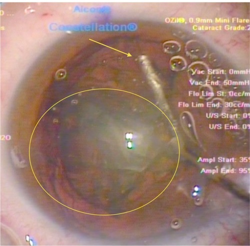
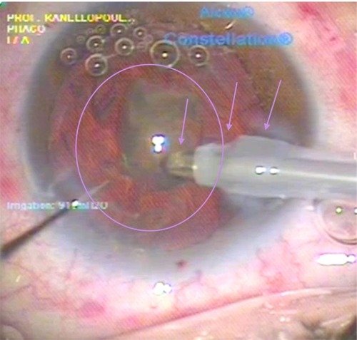
Figure 5 Last step of the nanosecond laser cataract quadrant removal. The last cataract quadrant left within the eye is seen here (purple oval) engaged by the aspiration of the probe (left purple arrow). The middle purple arrow points to one of the two silicone probe sleeve openings providing the coaxial irrigation. Finally, the rightmost purple arrow points to the hydration of the femto-created cornea incision, seen as clouding. This clouding of the incision margins is purely hydration, because this nanosecond laser probe does not emit any heat, as the laser energy is transmitted through fiber optics within the probe and released just at the edge of the probe onto the titanium target within the probe shown in .