Figures & data
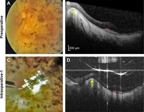
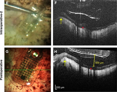
Figure 1 Argus II prosthesis repositioning.
Notes: (A) Preoperative color fundus photo of the left eye of a 66-year-old man with end-stage retinitis pigmentosa. (B) Preoperative spectral-domain optical coherence tomography (OCT) image showing sloping of the eye wall consistent with a posterior staphyloma. The elevated edge of the staphyloma (yellow arrow) and sub-retinal hyper-reflective material (red asterisk) are also in subsequent OCT images (D, F, and H) as landmarks showing similar scan locations. Note that all OCT images are shown in the standard format with elongated axial dimensions that exaggerate the distance between the prosthesis and the retinal surface. (C) Intrasurgical video-still image showing array malrotation over the optic nerve. (D) Intraoperative hand-held spectral-domain OCT image captured just after the moment in surgery imaged in (C), showing the array propped-up by the edge of the staphyloma. (E) Intrasurgical video-still image after array unrotation showing optimal positioning in the macula. (F) Intraoperative hand-held spectral-domain OCT captured just after the moment in surgery imaged in (E), showing the array free from the staphyloma edge. (G) Color scanning laser ophthalmoscopy image captured 3 months after surgery showing sustained optimal array positioning. The green line represents the OCT scan location shown in (H). (H) Spectral-domain OCT image 3 months after surgery confirming the array remains free from the staphyloma edge. The array does not fully contact the retina, and maximal distance between the array and retinal surface measures 500 µm (yellow calipers).