Figures & data
Table 1 List of Some Devices and Techniques Reported in the Literature to Aid the Scleral Lens Fitting Process and Evaluate the on-Eye Lens Fitting and Ocular Surface Physiology After Scleral Lens Wear
Figure 1 Measurement of post-lens fluid reservoir thickness (yellow), scleral lens thickness (green), and corneal thickness (blue) with the built-in software calipers of a commercially available AS-OCT device. It is essential to identify the anterior and posterior scleral lens surfaces and anterior and posterior corneal surfaces for the different measurements. Image credit: Rute Araújo.
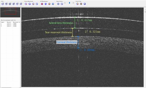
Figure 2 Schematic diagram and real photography of an optic section using fluorescein (left) and without fluorescein (right). The white arrows represent scleral lens thickness, the red arrows represent post-lens fluid reservoir thickness, and the black arrows represent corneal thickness.
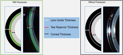
Figure 3 (A) High with the rule toricity: in this case, the orientation of the toricity is the same in the cornea and in the sclera (ESP); (B) scleral asymmetry in a keratoconus patient (Pentacam). Image credits: Daddi Fadel.
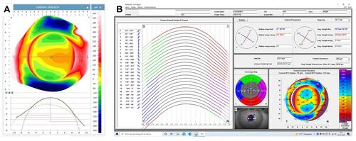
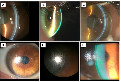
Figure 4 Slit lamp images of (A) conjunctival compression with conjunctival prolapse (arrow); (B) sectorial compression; (C) conjunctival impingement of a scleral lens; (D) lens edge lift – note the excessive fluorescein pooling under the haptic zone; (E) lens edge lift with small air bubbles; (F) lens edge lift in one Meridian while the lens is well aligned in the opposite Meridian; (G) air bubble entering into the post-lens fluid reservoir due to a poorly aligned lens. Image credits (A–F) - Daddi Fadel; (G) – Rute Araújo.
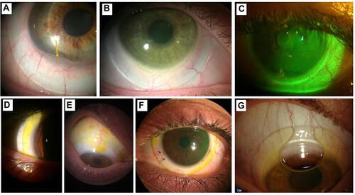
Figure 5 (A) Particles (midday fogging) due to sub-optimal lens alignment; (B) significant presence of particles; (C) milky post-lens fluid reservoir; (D) lipid deposits; (E) poor wettability of SL front surface; (F) SL with front surface debris and scratches. Image credits: (A–E) – Daddi Fadel; (F) – Melissa Barnett.