Figures & data
Figure 1 Interprosthetic femur fracture classification as described by Pires et al.
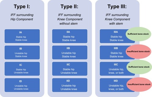
Figure 2 Preoperative radiographs (A, B) demonstrating a long spiral oblique interprosthetic fracture with apex posterior angulation. A laterally based femoral locking plate was used for internal fixation of this fracture (C, D) with the addition of interfragmentary lag and position screws.
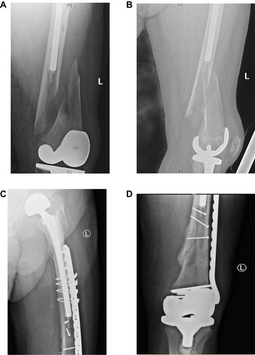
Figure 3 Preoperative anteroposterior (A) and lateral (B) radiographs showing plate osteosynthesis with a lateral locking plate and high screw density and thus stiff construct, resulting in a failure of fixation. Anteroposterior (C, D) radiographs of the revision construct demonstrating interfragmentary screws, decreased screw density and construct stiffness, and appropriate prosthesis overlap.
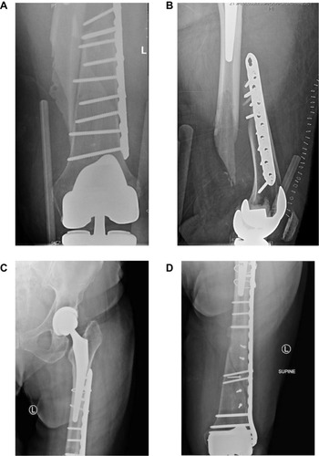
Figure 4 Anteroposterior radiograph of the proximal femur demonstrating periprosthetic fracture fixation around a long, cemented hip stem. Unicortical screws (outlined by red box) and supplemental cables are useful in this situation with limited bone stock around the stem and a stiff cement mantle.
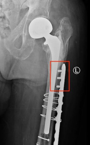
Figure 5 Anteroposterior (A, B) and lateral (C) radiographs of a distal periprosthetic femur fracture fixed with a short retrograde nail and supplemented with a long lateral locking plate in a patient with osteoporotic bone. The lateral radiograph demonstrates the staggered screw holes to maximize coverage around the nail and hip stem. (Image Courtesy: Derek J. Donegan, MD).
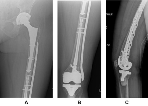
Figure 6 Anteroposterior (A) and lateral (B) radiographs of a stemmed revision total knee arthroplasty following periprosthetic fracture around a loose total knee prosthesis. Fixation is supplemented with a long lateral locking plate and several adaption plates to maximize screw purchase around the stems. Abundant callus is noted around the stem junction indicating a robust healing response.
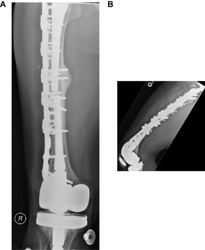
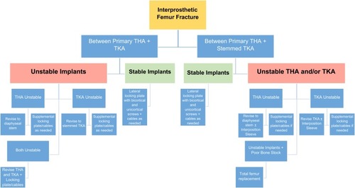
Figure 7 Authors’ preferred management strategy for fixation of interprosthetic femur fractures based upon fracture location, implant stability, and bone stock.