Figures & data
Figure 1 Classification of the stenosing airway disease by the type of airway involvement.
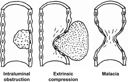
Table 1 Type of airway stenosis and treatment of choice
Table 2 Hugh-Jones classification for assessment of breathlessness on the basis of daily activities
Figure 2 (A) Three-dimensional computed tomography (CT) scan showed the narrowest part of the trachea present beneath the sternum. (B) Axial CT scan was done. A mass can be seen on the right side of the trachea, and due to the mass the trachea is deviated to the left side, compromising the airway tract before placement of the tracheobronchial stent. (C) After the placement of the tracheobronchial stent, the airway was recovered. (D) Dumon Silicone stent.
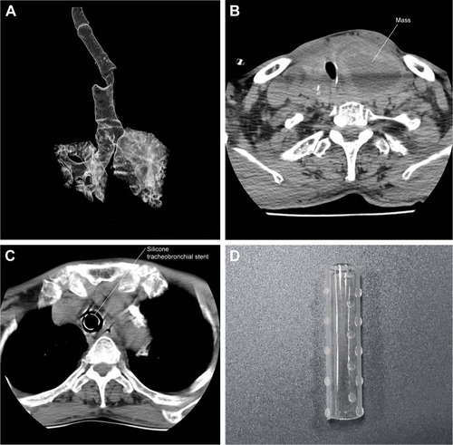
Figure 3 Bronchoscopic examination through the nose (A) showed that the trachea was depressed. (B) Silicone tracheobronchial stent of diameter 16×14×16 mm and length 15×20×15 mm was placed with the help of the bronchoscope. (C) Tracheobronchial stent placed on stenosed trachea site. (D) Final image after placement of the tracheobronchial stent.
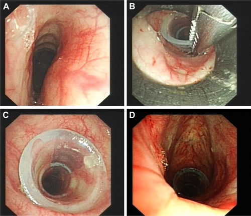
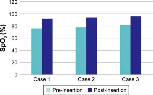
Figure 4 Improvement of oxygen saturation value (pre-insertion and post-insertion).