Figures & data
Table 1 Comparison of relevant indexes between navigation-assisted operation and the usual operation
Table 2 VAS score before and after the navigation aided styloidectomy
Figure 1 Preoperative analysis of the ESP in navigation workstation.
Abbreviations: 3D-CT, three-dimensional computed tomography; ESP, elongated styloid process; SP, styloid process.
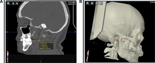
Figure 2 Intraoperative application of surgical navigation to orient the elongated SP.
Abbreviation: SP, styloid process.
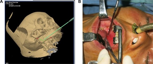
Figure 3 The intraoperative navigation was applied to expose the ESP by intraoral approach.
Abbreviations: ESP, elongated styloid process; SP, styloid process.
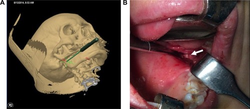
Figure 4 Images for preoperative analysis of the ESP and the virtual surgery plan.
Abbreviation: 3D-CT, three-dimensional computed tomography; ESP, elongated styloid process; SP, styloid process.
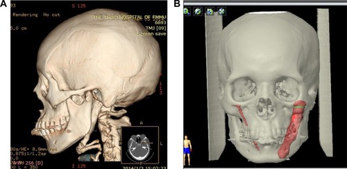
Figure 5 During the surgery, a fine round bur was matched with the navigation system so that it could be used as an EM pointer and its track could simultaneously be seen on the screen.
Abbreviations: EM, electromagnetic; SP, styloid process.
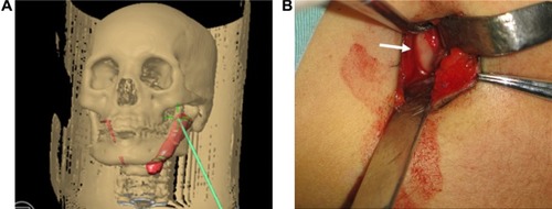
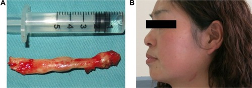
Figure 6 The resected giant elongated styloid process and the small cervical skin scar after extraoral approach.