Figures & data
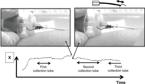
Figure 1 Location of the marker used and itemization of vacuum blood collection tube movement in the venipuncture procedure.
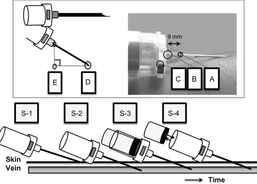
Table 1 Subjects undergoing venipuncture, distance of needle movement, and puncture angle
Table 2 Summation of total needle movement distance
Figure 2 X-axis: maximum of accumulated movement. (a) shows the start and (b) shows the end of the movement.
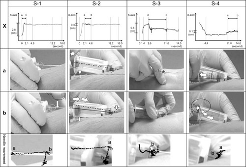
Figure 3 Y-axis: maximum of accumulated movement. (a) shows the start and (b) shows the end of the movement.
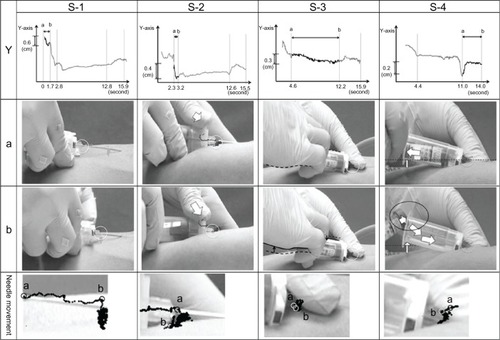
Figure 4 Searching: location of the welded part of the needle at the point where the blood collection tube entered the tip of the holder, and the location of the sticker placed on the holder. (1) the first puncture is not successful; (2) the second puncture is not successful; (3) the third puncture is successful.
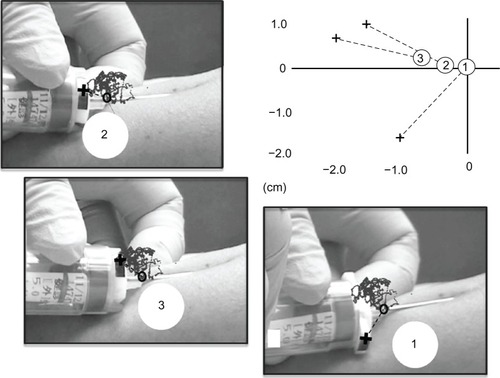
Figure 5 A case in which the hands were not changed.