
Figures & data
Figure 1 The timing and cell types involved in wound repair demonstrating the role of WBC (including neutrophils, macrophages, and lymphocytes) in successful healing.
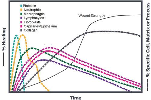
Table 1 Growth Factors and Their Proposed Functions in PRP
Table 2 Survey for Canine Owners at Beginning of Lameness Evaluations
Table 3 Physical/Neurologic Examination Steps
Figure 2 Blood draw process from canine patients. (A) Blood draw sites were prepared by clipping area over the jugular vein and then the skin was aseptically cleaned. (B) The needle was inserted into the jugular vein and the syringe was slowly pulled back to check for a flash of blood to confirm needle placement. (C) The blood was slowly drawn while rocking syringe to ensure mixture of blood and anti-coagulant.
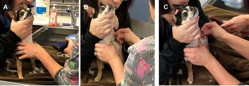
Figure 3 Representative pictures of 60mL L-PRP device processing: 1) a 18-gauge needle was attached to a 60mL syringe and 5–8mL of ACD-A was withdrawn. 2) The cap was unscrewed on center port of the L-PRP device and the green packaging post was discarded. Blood was slowly loaded into the center port. The syringe was removed and the tethered cap was attached to its port. 3) The L-PRP device was placed into the centrifuge and balanced with a counterbalance. 4) The L-PRP device was spun in centrifuge at 3200 RPM for 15 minutes. 5) The yellow cap was removed on the side port and a 30mL syringe was connected. The device was tilted at an angle, avoiding inverting to keep top blue vent dry, and all of the platelet-poor plasma (PPP) was removed. The yellow cap was replaced. 6) The red cap was removed on the side port and a 10mL syringe was connected. 2mL of PRP was withdrawn and syringe was left attached. With the 10mL syringe attached, the PRP was suspended by gently shaking L-PRP device for 30 seconds. The remaining PRP suspension was extracted into the attached 10mL syringe.
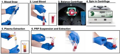
Figure 4 Representative pictures of APS device processing: 1) The APS Concentrator device was gently shaken to ensure beads were evenly distributed across bottom of top chamber. The yellow cap was unscrewed on the APS Concentrator device and filled with the output of L-PRP device from the 10mL syringe. The 10mL syringe was removed and the tether cap on port was attached. The paddle was spun until the cell solution was fully mixed with beads. 2) The concentrator was placed into the centrifuge. The centrifuge was balanced with a counterbalance. The concentrator device was spun for 2 minutes at 2000 RPM. 3) The APS was gently resuspended in the bottom of the APS Concentrator. The red cap was unscrewed and connected to a sterile 10mL syringe. The APS was extracted.
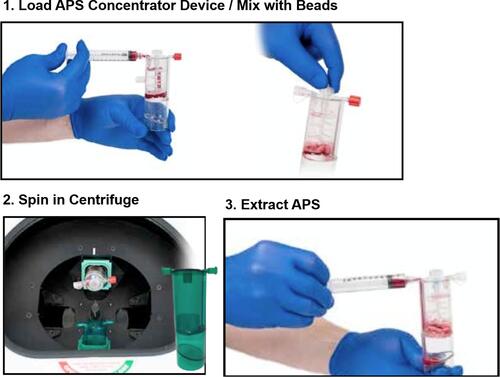
Table 4 Procedures Used During Canine Joint Injections
Table 5 Frequency of L-PRP Applications in Our Practice Including Tendon/Ligament Applications, OA, and Joint Applications
Table 6 Description of APS Use in for a Variety of Orthopedic Conditions Including Tendon/Ligament Applications, OA, and Joint Applications