Figures & data
Figure 1 Crystal structures of a range of cage proteins. (a) Dps protein (pdb 2bjy (CitationIlari et al 2005)), diameter 9 nm; (b) Ferritin (pdb 2za6 (CitationYoshizawa et al 2007)) diameter 12 nm; (c) Cowpea chlorotic mottle virus (CCMV, pdb 1cwp (CitationSpeir et al 1995)), diameter 26 nm; and (d) Cowpea mosaic virus (1NY7 (CitationLin et al 1999)), diameter 28 nm. In (d), red spheres show the N-terminal glycine that points into the central cavity. Dark blue spheres show the C-terminal lysine on the external surface.
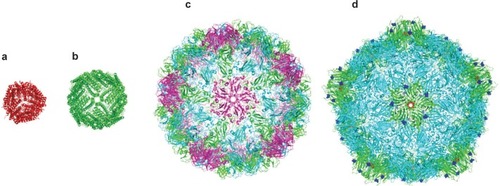
Figure 2 Transmission electron micrographs of “Ball-and-Spike” protein shown in two different orientations. Inset shows an interpretation of the micrograph using existing crystal structures of gp5c and Dps. Reproduced with permission from CitationSugimoto K, Kanamaru S, et al 2006. Construction of a ball-and-spike protein supramolecule13. Angew Chem Int Ed, 45:2725–8. Copyright ©. Wiley-VCH Verlag GmbH and Co. KGaA.
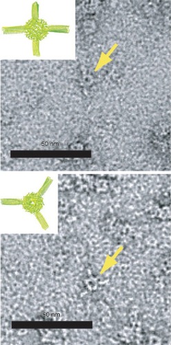
Figure 3 Transmission electron micrographs of ferritin (left) and Dps (right) both filled with CdS cores (CitationIwahori et al 2007; CitationIwahori and Yamashita 2007). Figure courtesy of Kenji Iwahori.
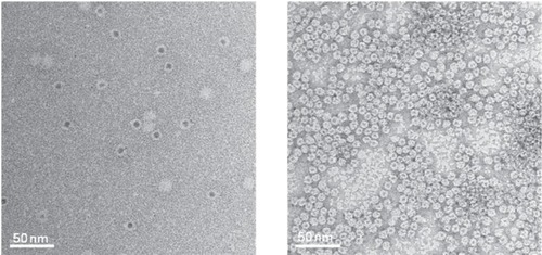
Figure 4 CPMV capsids can be layered on a gold surface with each layer carrying a different modification. In this example, the biotinylated base layer is unlabeled, the second layer is labeled with a red fluorescent dye (AlexaFluor dye AF568) and a third layer with a green fluorescent dye (AF568). Layers are bridged by streptavidin (black cross). Fluorescence imaging microscopy (left) shows that each layer is homogenous. Scale bar is 10 μm. Reproduced with permission from CitationSteinmetz et al 2006a. Plant viral capsids as nanobuilding blocks: construction of arrays on solid supports. Langmuir, 22:10032–37. Copyright © 2006. American Chemical Society.
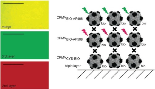
Figure 5 SV40 can form spherical or tubular structures depending on buffer conditions. Left: SV40VP1 pentamers assembled into tubular structure in vitro. Middle: SV40VP1 pentamers assembled into 40 nm spherical particles in vitro in the presence of DNA. Right: VP1 assembled into VLPs (Virus Like Particles) inside insect cells. In all cases, scale bar is 100 nm. Images courtesy of Hiroko Tsukamoto.
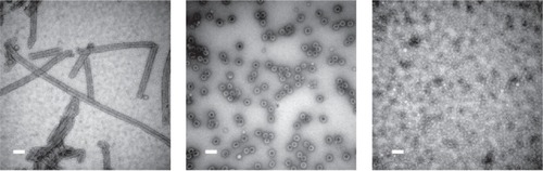
Figure 6 Crystal structures of various ring-shaped proteins. (a) wild-type TRAP protein (pdb 1qaw (CitationChen et al 1999), diameter approximately 8 nm); (b) mutant 12-membered TRAP protein (pdb 2zd0 (CitationWatanabe et al 2008)); (c) PCNA (pdb 1axc (CitationGulbis et al 1996)); (d) RAD52 (pdb 1kno (CitationKagawa et al 2002)), (e) GROEL (pdb 1grl (CitationBraig et al 1994)). All proteins shown approximately to scale.
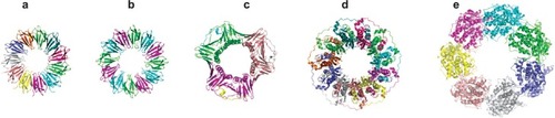
Figure 7 Cross-sectional TEM image of gold nanodots captured by TRAP and embedded in the SiO2 layer of a MOS capacitor. Reproduced with permission from CitationHeddle et al 2007. Using the ring-shaped protein TRAP to capture and confine gold nanodots on a surface. Small, 3:1950–6. Copyright © 2007. Wiley-VCH Verlag GmbH and Co. KGaA.
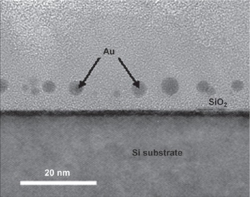
Figure 8 Aurothioglucose-stained TEM image showing TMV with biomineralized Co-Pt forming a nanowire in its cavity. Scale bar is 50 nm. Reproduced with permission from CitationTsukamoto et al 2007b. Synthesis of CoPt and FePt3 nanowires using the central channel of tobacco mosaic virus as a biotemplate. Chem Mater, 19:2389–91. Copyright © 2007. American Chemical Society.
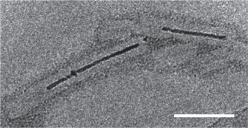
Figure 9 (a) A schematic showing the polymerization of SP1 rings (shown in blue) via interaction with gold nanodots (yellow) placed in the central cavity of the ring; (b) a TEM image of tube-like chains (highlighted by red lines) of SP1 rings (light grey) mediated by gold nanodots (black dots). Reprinted in part with permission from CitationMedalsy et al 2008. SP1 protein-based nanostructures and arrays. Nano Lett, 8:473–7. Copyright © 2008. American Chemical Society.
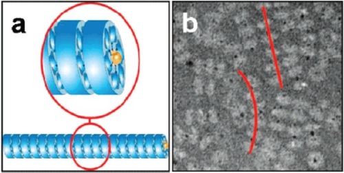
Figure 10 (A) Crystal structure of hcp (pdb 1y12 (CitationMougous, Cuff et al 2006)). Shown from the top, bottom and side. Dimensions are given in nanometers. Each monomer is shown in a different color and three monomers are removed for the side view. Based on the packing of the rings in the crystal structure into tubes (B) residues R157 and G90 were mutated to cysteine residues to facilitate tube formation via disulfide bond formation (C) Reproduced with permission from CitationBallister et al 2008. In vitro self-assembly of tailorable nanotubes from a simple protein building block. Proc Nat Acad Sci U S A, 105:3733–8. Copyright © 2008. National Academy of Sciences, USA.
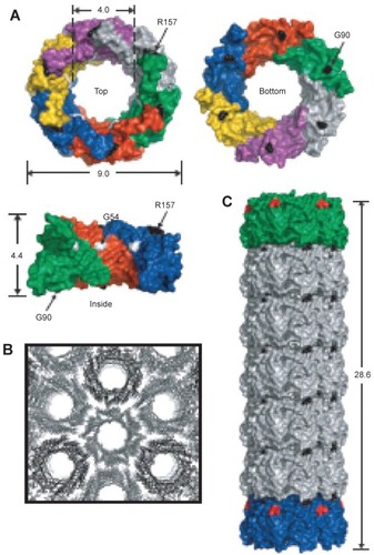
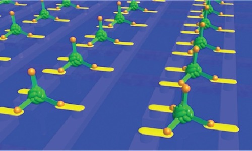
Figure 11 Imagined array of ball and spike protein binding to nanodots and electrodes that interface it to a microelectronic device. Image courtesy of Ichiro Yamashita.