Figures & data
Figure 1 Eye dropper bottle.
Notes: The eye dropper bottle models were made of polyethylene resins, and were cylindrical-shaped with a dent on their trunk. Wall thickness of the bottle was 0.7 mm, and bottle volume was 8 mL.
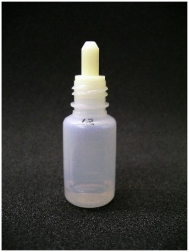
Figure 2 Structure of eye dropper bottle.
Notes: Outer diameter of the tip of model eye dropper nozzle was standardized to be 3.1 mm. Concerning inner structure, the bottles had three different types of internal space volume of the nozzle (7 mm3, 30 mm3 and 55 mm3) and six different inner aperture diameters (0.2 mm, 0.3 mm, 0.4 mm, 0.5 mm, 0.6 mm and 0.7 mm). In total, 18 patterns of nozzle models were molded.
Abbreviations: IAD, inner aperture diameter; ISV, internal space volume; ODT, outer diameter of tip.
Abbreviations: IAD, inner aperture diameter; ISV, internal space volume; ODT, outer diameter of tip.
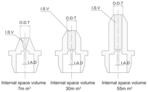
Figure 3 Dispensing time measuring apparatus.
Notes: A model bottle filled with the test solution was placed in the inverted position at the midportion between the site applied the pressure by a metal pressure rod (A; 10 mm in diameter) connected to an air cylinder and the tip of a digital force gauge (C). The midsection of the bottle trunk was pressed and a drop of solution was dribbled mechanically. Digital force gauge detected the application of pressure, and a timer counter was activated. After the pressure in the bottle increased and a drop of solution was dribbled, an infrared ray sensor (B) detected the drop and the timer counter stopped.
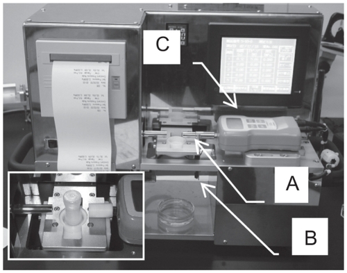
Figure 4 Dispensing time under condition of changing inner aperture diameter, thrust load pressure, and types of solution.
Notes: Mean dispensing time using fixed volumes of internal space (30 mm3) and fluid volume (5 mL), and variable inner aperture diameters (IADs) as well as pressures to the bottle (A: filtrate water, B: surfactant solution); error bars indicate standard deviation. Asterisks indicate statistically significant differences: ***P < 0.001; IAD of 0.2 mm vs IAD of 0.3 mm, **P < 0.01; IAD of 0.3 mm vs IAD of 0.4 mm.
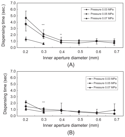
Figure 5 Dispensing time under condition of changing internal nozzle volume, inner aperture diameter, and types of solution.
Notes: Dispensing time (mean ± SD) under a condition of a fixed pressure thrust load (0.05 MPa) and variable internal nozzle volumes and inner aperture diameters. (□: 0.2 mm, ▨: 0.5 mm, ▪: 0.7 mm) (A: filtrate water, B: surfactant solution); error bars indicate standard deviation. Asterisks indicate statistically significant differences: *P < 0.05, **P < 0.01, ***P < 0.001.
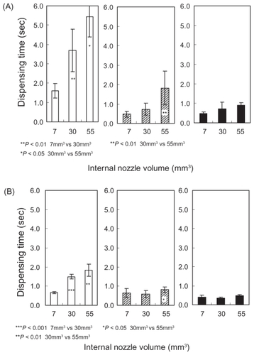
Figure 6 Dispensing time under condition of changing fluid volume, inner aperture diameter, and types of solution.
Notes: Dispensing time (mean ± SD) under a condition of fixed internal nozzle volume (30 mm3) and pressure thrust load (0.05 MPa), and variable fluid volumes as well as inner aperture diameters. (□: 0.2 mm, ▨: 0.5 mm, ▪: 0.7 mm) (A: filtrate water, B: surfactant solution); error bars indicate standard deviation. Asterisks indicate statistically significant difference: *P < 0.05; fluid volume of 3 mL vs fluid volume of 5 mL, **P < 0.01; fluid volume 1 mL vs fluid volume of 3 mL.
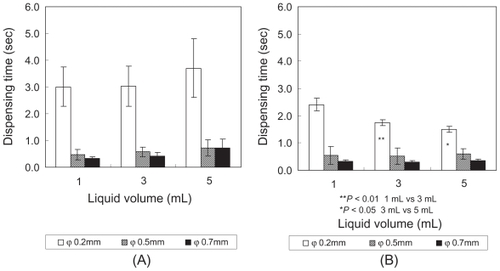
Table 1 Regression analysis regarding the dispensing time