Figures & data
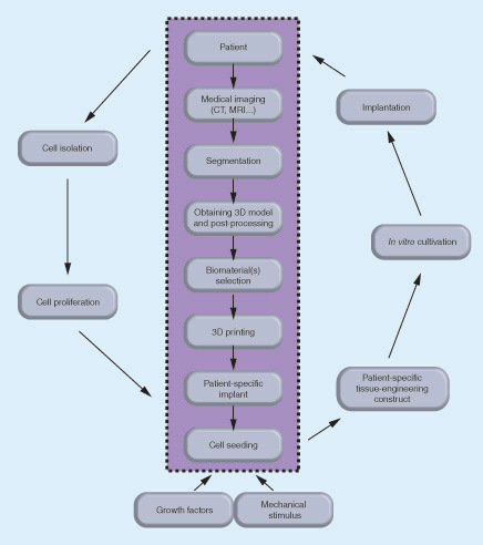
The data obtained from medical imaging of the patient's intervertebral disc (IVD) are segmented and processed into a 3D model to be used in 3D printing the selected biomaterial(s) of a patient-specific IVD implant. Different types of biomaterials can be used for reproducing the annulus fibrosus and nucleus pulposus. The autologous cells are isolated from the patient, proliferated in vitro and introduced into patient-specific scaffold in the presence of growth factors and mechanical stimulus. The tissue engineered patient-specific construct cultured in vitro can be then implanted into the patient.
AF: Annulus fibrosus; IVD: Intervertebral disc; NP: Nucleus pulposus.
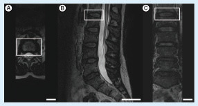
Images taken from the (A) axial, (B) sagittal and (C) coronal planes. The L1–L2 intervertebral disc was indicated by the white rectangle (scale bars: 4 cm).
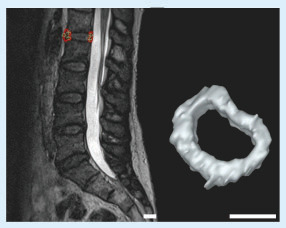
Left: L1–L2 intervertebral disc of the patient. Right: the 3D model of the intervertebral disc after completing the segmentation (scale bars: 2 cm).
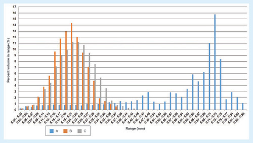
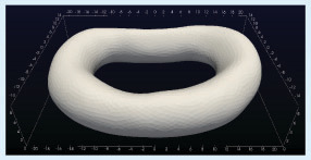
The numbers correspond to millimeter.
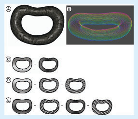
(A) The wireframe 3D model of the intervertebral disc (IVD) of the patient; (B) the layers of the 3D IVD model after slicing of the 3D model into layers with colors changing from red to blue indicating the top and the bottom layer, respectively; the illustration of the alternating layers in the three architectures: architectures A–C with (C) 0°/90°, (D) 0°/60°/120° and (E) 0°/45°/90°/135° strand structures, respectively.
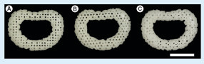
(A) Architecture A (0°/90° strand structure). (B) Architecture B (0°/60°/120° strand structure). (C) Architecture C (0°/45°/90°/135° strand structure) (scale bars: 1 cm).
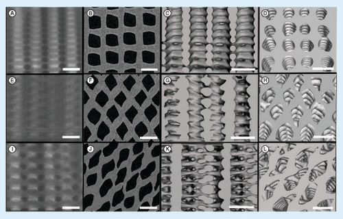
(Top row: A–D) A (0°/90° strand structure), (middle row: E–H), B (0°/60°/120° strand structure) and (bottom row: I–L) C (0°/45°/90°/135° strand structure): the x-ray images (A, E and I), the 2D reconstructed microcomputed tomography images (B, F and J), the 3D reconstructed images showing the structures from side (C, G and K) and top (D, H and L) (scale bars: 1 mm).
(A) (0°/90° strand structure), (B) (0°/60°/120° strand structure) and (C) (0°/45°/90°/135° strand structure).