Figures & data
Figure 1. Electrode array types.
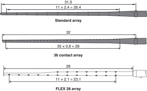
Table I. Technical specifications of the electrode types.
Figure 2. Measurement of full insertion depth of the electrode. A standard electrode array with the measures (mm) is shown in (A). On the cone-beam computed tomography (CBCT) image (B), three contacts (C10–C12) were outside the round window (RW) and the intracochlear measures started from the RW.
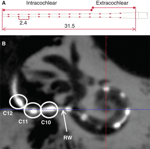
Table II. Image quality demonstrated by average levels of five evaluators using a rating system from 5 to 1 in descending order.
Figure 3. Fine cochlear structures demonstrated by cone-beam computed tomography (CBCT). All specified landmarks were clearly identified in all six temporal bones (TB). BW, bony wall; Cont, contours of cochlear implant; Mod, modiolus; OSL, osseous spiral lamina.
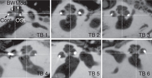
Figure 4. Critical cochlear assessments on cone-beam computed tomography (CBCT) images. ‘A’ value (A), cochlear height (B), insertion depth for the first 360° insertion angle (C), and distance between the electrode contacts and the modiolus (D) are demonstrated (in mm). Ap, apex; Cont, contours of cochlear implant; Fund, fundus; LW, lateral wall; Mod, modiolus; RWM, round window membrane.
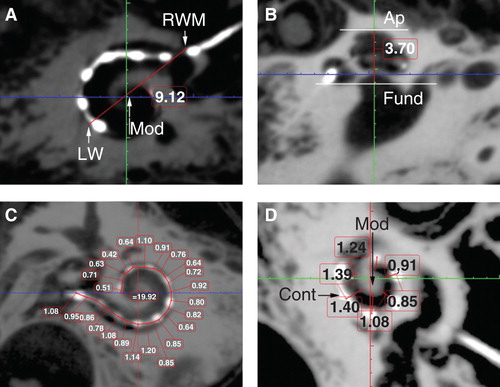
Figure 5. Correlations between ‘A’ value and cochlear implant electrode array insertion parameters measured on cone-beam computed tomography (CBCT) images. Good correlations appeared between A value and cochlear height shown (A), and between A value and insertion depth for the first 360° insertion angle (B). Sample 2 was removed.
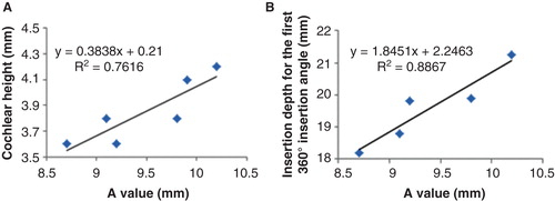
Table III. Insertion angle and insertion depth of the electrode arrays with number of contact pairs outside the cochlea.
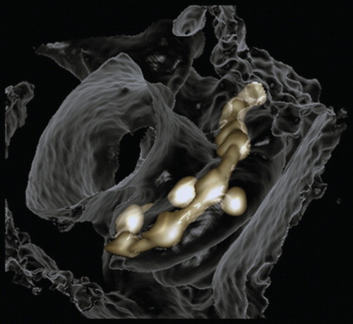
Figure 6. 3D reconstruction of cone-beam computed tomography (CBCT) images showing spatial correlation between the electrode contacts and the osseous cochlear modiolus.