371
Views
10
CrossRef citations to date
0
Altmetric
Original

Characteristics and performance evaluation of the capacitive Contact Flexible Microstrip Applicator operating at 70 MHz for external hyperthermia

, , , , , , & show all
Pages 542-553 | Received 10 Oct 2007, Accepted 21 May 2009, Published online: 24 Oct 2009

Figures & data

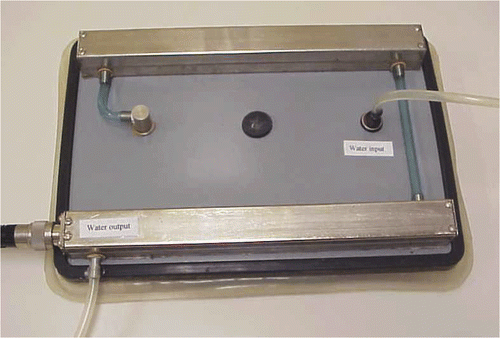
Figure 1. The capacitive Contact Flexible Microstrip Applicator, CFMA-70.

Figure 1. The capacitive Contact Flexible Microstrip Applicator, CFMA-70.

Figure 2. Schematic representation of the mechanical construction of the CFMA-70 and its water cooling circuit.
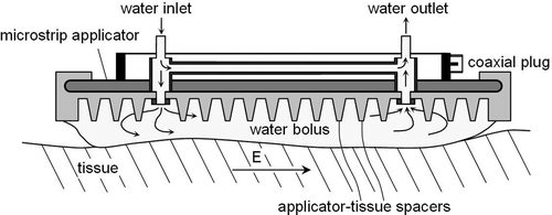
Figure 2. Schematic representation of the mechanical construction of the CFMA-70 and its water cooling circuit.

Figure 3. Schematic representation of the experimental set-up used for measurement of the E-field pattern emanating from the CFMA-70. The elliptical phantom (cross section 24 cm × 36 cm, length 84 cm) has a 2-mm PVC wall and is filled with a saline solution. In the lower-right transparent representation the scanning planes are visualised.
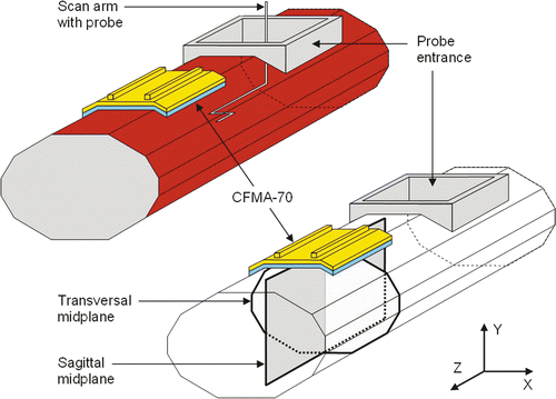
Figure 3. Schematic representation of the experimental set-up used for measurement of the E-field pattern emanating from the CFMA-70. The elliptical phantom (cross section 24 cm × 36 cm, length 84 cm) has a 2-mm PVC wall and is filled with a saline solution. In the lower-right transparent representation the scanning planes are visualised.

Figure 4. Contour plots of the E-field pattern emanating from the CFMA-70 applicator with a 1-cm thick bolus. The Z-component of the E-field in the origin of the phantom is normalised to 100%. Top graph: Z-component of the E-field in the XY-plane; Middle: Z-component of the E-field in the YZ-plane; Bottom: Y-component of the E-field in the YZ-plane. For all graphs the interval between contour lines is 50 and 25 for contours above and below 100 respectively.
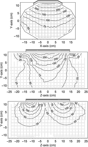
Figure 4. Contour plots of the E-field pattern emanating from the CFMA-70 applicator with a 1-cm thick bolus. The Z-component of the E-field in the origin of the phantom is normalised to 100%. Top graph: Z-component of the E-field in the XY-plane; Middle: Z-component of the E-field in the YZ-plane; Bottom: Y-component of the E-field in the YZ-plane. For all graphs the interval between contour lines is 50 and 25 for contours above and below 100 respectively.

Figure 5. Contour plots of the SAR patterns in the XY-plane and YZ-plane emanating from the CFMA-70 applicator with a 1-cm thick bolus. The SAR is normalised to 100% at 1 cm depth in the saline solution below the centre of the applicator.
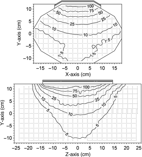
Figure 5. Contour plots of the SAR patterns in the XY-plane and YZ-plane emanating from the CFMA-70 applicator with a 1-cm thick bolus. The SAR is normalised to 100% at 1 cm depth in the saline solution below the centre of the applicator.

Figure 6. PDSAR profiles, SAR as a function of distance below the phantom surface, for CFMA-70 and waveguide. Profiles are given for two different saline solutions. The CFMA-70 has been positioned on the top of the phantom surface (low curvature) as well as on its side (higher curvature). The SAR is normalised to 100% at 1 cm depth in the saline solution.
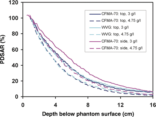
Figure 6. PDSAR profiles, SAR as a function of distance below the phantom surface, for CFMA-70 and waveguide. Profiles are given for two different saline solutions. The CFMA-70 has been positioned on the top of the phantom surface (low curvature) as well as on its side (higher curvature). The SAR is normalised to 100% at 1 cm depth in the saline solution.

Figure 7. Contour plots of the E-field pattern emanating from a 70 MHz waveguide with a 4-cm thick bolus. The Z-component of the E-field in the origin of the phantom is normalised to 100%. Top graph: Z-component of the E-field in the XY-plane; Middle: Z-component of the E-field in the YZ-plane; Bottom: Y-component of the E-field in the YZ-plane. For the top and middle graphs the interval between contour lines is 50 and 25 for contours above and below 100 respectively. For the bottom graph the interval between contour lines is 10.
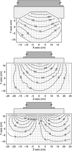
Figure 7. Contour plots of the E-field pattern emanating from a 70 MHz waveguide with a 4-cm thick bolus. The Z-component of the E-field in the origin of the phantom is normalised to 100%. Top graph: Z-component of the E-field in the XY-plane; Middle: Z-component of the E-field in the YZ-plane; Bottom: Y-component of the E-field in the YZ-plane. For the top and middle graphs the interval between contour lines is 50 and 25 for contours above and below 100 respectively. For the bottom graph the interval between contour lines is 10.

Figure 8. Contour plots of the SAR pattern in the XY-plane and YZ-plane emanating from the 70 MHz waveguide with a 4-cm thick bolus. The SAR is normalised to 100% at 1 cm depth in the saline solution below the centre of the applicator.
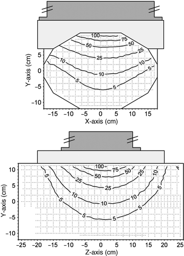
Figure 8. Contour plots of the SAR pattern in the XY-plane and YZ-plane emanating from the 70 MHz waveguide with a 4-cm thick bolus. The SAR is normalised to 100% at 1 cm depth in the saline solution below the centre of the applicator.

Figure 9. Example of clinical application. CT-slice of the breast with a schematic representation of applicator and additional bolus. The applicator and bolus are kept in position using a belt around the thorax. Note the two catheter tracks in the breast for placement of thermocouple probes (third track not visible in this CT-slice).
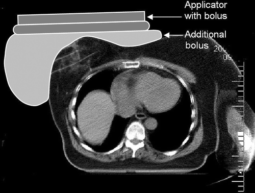
Figure 9. Example of clinical application. CT-slice of the breast with a schematic representation of applicator and additional bolus. The applicator and bolus are kept in position using a belt around the thorax. Note the two catheter tracks in the breast for placement of thermocouple probes (third track not visible in this CT-slice).

Table I.  Properties of the CFMA-70 and CFMA-434 applicators. Data regarding the CFMA-434 is taken from Lamaitre et al. Citation[7].
Reprints and Corporate Permissions

Please note: Selecting permissions does not provide access to the full text of the article, please see our help page How do I view content?

To request a reprint or corporate permissions for this article, please click on the relevant link below:

Academic Permissions

Please note: Selecting permissions does not provide access to the full text of the article, please see our help page How do I view content?

Obtain permissions instantly via Rightslink by clicking on the button below:

If you are unable to obtain permissions via Rightslink, please complete and submit this Permissions form. For more information, please visit our Permissions help page.