1,152
Views
77
CrossRef citations to date
0
Altmetric
Original

A literature survey on indicators for characterisation and optimisation of SAR distributions in deep hyperthermia, a plea for standardisation

, , &
Pages 593-608 | Received 23 Oct 2007, Accepted 08 Jun 2009, Published online: 24 Oct 2009

Figures & data

Figure 1. Outline of the study.

Figure 1. Outline of the study.

Table I.  Characteristics of the 36 patient models that were used to verify the found indicators. Averages and standard deviations are given.

Figure 2. Axial view of the BSD2000 Sigma 60 applicator, with the four channels, each connected to two antennas and a combined patient-applicator model.
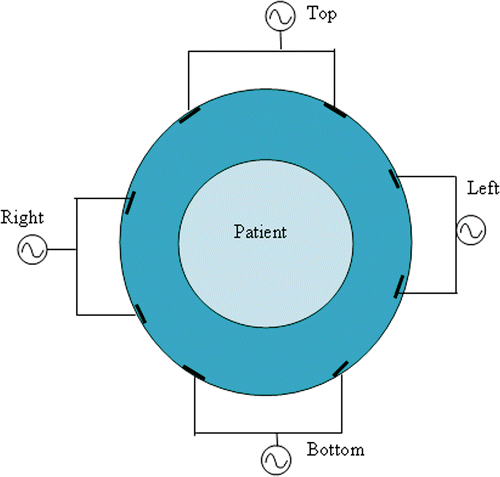
Figure 2. Axial view of the BSD2000 Sigma 60 applicator, with the four channels, each connected to two antennas and a combined patient-applicator model.

Table II.  Tissues, defined in the patient model and their electromagnetic and thermal properties at 77 MHz, 37 °C and under thermal stress Citation[34],Citation[44],Citation[45].

Table III.  Quality indicators found in literature with a short explanation of their functionality.

Figure 3. Illustration of SAR5 definition: SAR(tot)5 covers a substantial part of the target (A), and of 25%SAR targ max and 75%SAR targ max definition versus SAR25targ and SAR75targ definition (B). Both histograms are averages of 10 patient models.
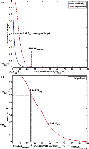
Figure 3. Illustration of SAR5 definition: SAR(tot)5 covers a substantial part of the target (A), and of 25%SAR targ max and 75%SAR targ max definition versus SAR25targ and SAR75targ definition (B). Both histograms are averages of 10 patient models.

Table IV.  Heuristic evaluation of the quality indicators from .

Table V.  Suggested modified and new quality indicators for characterisation and SAR optimisation.

Figure 4. Correlation of all indicators with target temperatures. Each indicator is individually plotted in a separate subfigure. Above each subfigure, the indicator number is depicted. R2 correlation coefficients in each subfigure indicate the amount of correlation between the respective indicator and the corresponding T50targ value.
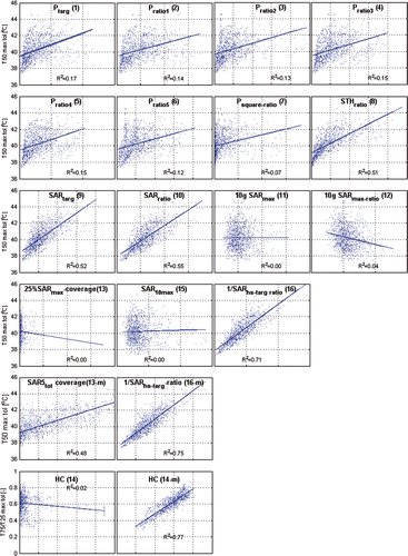
Figure 4. Correlation of all indicators with target temperatures. Each indicator is individually plotted in a separate subfigure. Above each subfigure, the indicator number is depicted. R2 correlation coefficients in each subfigure indicate the amount of correlation between the respective indicator and the corresponding T50targ value.

Figure 5. T50targ at the maximum patient tolerance, after optimisation with each indicator. The average T50targ over 36 patients is shown, together with SE of means as error bars.
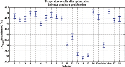
Figure 5. T50targ at the maximum patient tolerance, after optimisation with each indicator. The average T50targ over 36 patients is shown, together with SE of means as error bars.

Reprints and Corporate Permissions

Please note: Selecting permissions does not provide access to the full text of the article, please see our help page How do I view content?

To request a reprint or corporate permissions for this article, please click on the relevant link below:

Academic Permissions

Please note: Selecting permissions does not provide access to the full text of the article, please see our help page How do I view content?

Obtain permissions instantly via Rightslink by clicking on the button below:

If you are unable to obtain permissions via Rightslink, please complete and submit this Permissions form. For more information, please visit our Permissions help page.