Figures & data
Figure 1. A 513 element transducer. The focal point is 150 mm from the surface of the transducer. Elements of 1st, 10th, and 513th were used as the basis to calculate the phase and amplitude conditions of anti-focus later in this presentation.
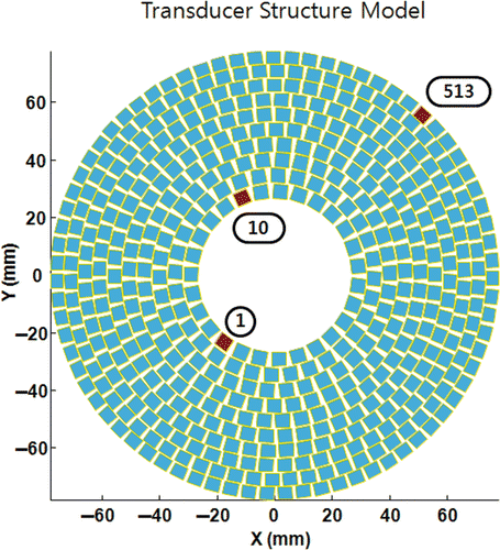
Table I. Parameters for bio heat transfer equation.
Table II. Foci and anti-focus arrangement for an application example.
Figure 2. Pressure field at the geometric focus of the transducer with the equal phase and amplitude condition on each element. (A) is the x-y plane (lateral) field and (B) is the x-z plane (axial) field.
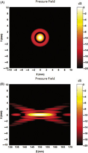
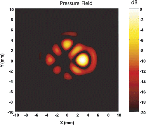
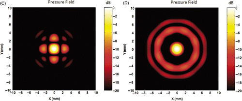
Figure 3. Pressure field of an anti-focus located at (0, 0, 150). (A) and (B) are the x-y and y-z plane field, respectively, obtained from M-order complex root of 1. (A) and (B) show that the zero pressure point is achieved by systematic shifting of the focus point. (C) and (D) are x-y and y-z plane field, respectively, obtained using ODRPI with the first element as the basis. (E) and (F) are x-y plane fields obtained using ODRPI with the 10th and the 513th element as the basis, respectively. (C) to (F) show the anti-focus with ODRPI is not a systematic shift of a focus. Additionally, the choice of the base element determines the overall shape of the field around the anti-focus point.
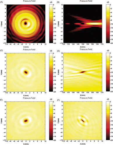
Figure 4. Amplitude and phase of each element for an anti-focus. (A) shows the normalised amplitude of each channel to generate the anti-focus, and (B) shows the relative phase of each channel. Only the amplitude of the base element is 1 and the amplitudes of all other elements are nominal and the phases are identical considering 2π periodicity, if ODRPI is used. On the other hand, an anti-focus can also be achieved by simple phase modulation with equal amplitude, if M-order complex root of 1 is used.
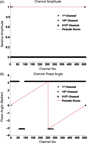
Figure 5. The simulated field obtained with phased conditions from ODRPI and the amplitude modified to 1. If each element is driven with phases from ODRPI and equal amplitudes, a focus can be generated instead of an anti-focus. Hence, the amplitude modulation is the main factor for a single anti-focus, if ODRPI is used.
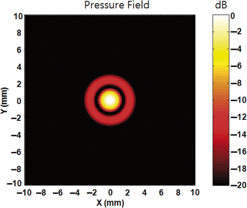
Figure 6. Pressure field of multiple foci. (A) is the field when foci are located at (1, 0, 150), (0, 1, 150), (−1, 0, 150), and (0, −1, 150). (B) is the field when foci are placed at (2.5, 0, 150), (0, 2.5, 150), (−2.5, 0, 150), and (0, −2.5, 150). Figures indicate a new focus can be formed by closely located foci. (C) shows a line of field at y = 0 from (A) (B). As can be seen in (C), the intended pressure value 1 was achieved at the control points (intended foci). This implies the individual pressure fields are independent from each other. (D) is the summation of the four single focus fields. The comparison between (B) and (D) indicates that the multi-foci field is almost identical with the summation of individual focus fields.
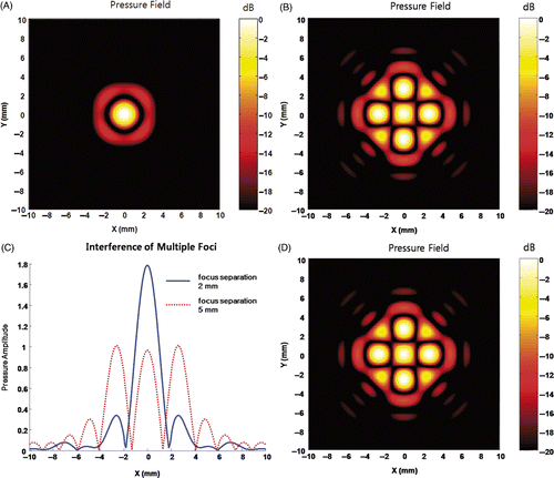
Figure 7. Pressure field of multiple anti-foci. (A) is the field when foci are located at (1, 0, 150), (0, 1, 150), (−1, 0, 150), and (0, −1, 150). (B) shows the field when foci are placed at (2.5, 0, 150), (0, 2.5, 150), (−2.5, 0, 150), and (0, −2.5, 150). (C) shows a line of field at y = 0 from (A) and (B). Figures indicate anti-foci are independent to each other. The comparison between (B) and (D) shows that the multiple anti-foci field can be approximated with a product of individual anti-focus fields.
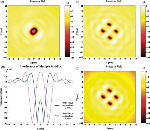
Figure 8. Pressure field of the combination of an anti-focus and multiple foci. With a single anti-focus at the (0, 0, 150), three different sets of four foci are applied to create (A)–(C). The first set is [(1, 0, 150), (0, 1, 150), (−1, 0, 150), (0, −1, 150)], the second set is [(2.5, 0, 150), (0, 2.5, 150), (−2.5, 0, 150), (0, −2.5, 150)], and the third set is [(3, 0, 150), (0, 3, 150), (−3, 0, 150), and (0, −3, 150)], respectively. (D) shows the centre line of the pressure field at y = 0. As shown in (D), if the distance between focus and anti-focus reaches 3 mm which is approximately the end of the first side lobe, the interference at control points becomes nominal.
![Figure 8. Pressure field of the combination of an anti-focus and multiple foci. With a single anti-focus at the (0, 0, 150), three different sets of four foci are applied to create (A)–(C). The first set is [(1, 0, 150), (0, 1, 150), (−1, 0, 150), (0, −1, 150)], the second set is [(2.5, 0, 150), (0, 2.5, 150), (−2.5, 0, 150), (0, −2.5, 150)], and the third set is [(3, 0, 150), (0, 3, 150), (−3, 0, 150), and (0, −3, 150)], respectively. (D) shows the centre line of the pressure field at y = 0. As shown in (D), if the distance between focus and anti-focus reaches 3 mm which is approximately the end of the first side lobe, the interference at control points becomes nominal.](/cms/asset/ea3eb61b-7504-48ac-9757-1b2f4ed5db29/ihyt_a_419009_f0008_b.gif)
Figure 9. Field map of the combination of an anti-focus and foci at higher frequency and modified amplitude condition. (A) shows the field with an anti-focus and four foci at [(1, 0, 150), (0, 1, 150), (−1, 0, 150), (0, −1, 150)] with a frequency of 3 MHz. (A) confirms that the recommended distance between anti-focus and focus is approximately the end of the first side lobe of the transducer. (B) was obtained by modifying the amplitude condition to 1. An anti-focus and four foci were successfully created as intended with additional side lobes. This indicates that a switching type amplifier can be effectively used with anti-foci.
![Figure 9. Field map of the combination of an anti-focus and foci at higher frequency and modified amplitude condition. (A) shows the field with an anti-focus and four foci at [(1, 0, 150), (0, 1, 150), (−1, 0, 150), (0, −1, 150)] with a frequency of 3 MHz. (A) confirms that the recommended distance between anti-focus and focus is approximately the end of the first side lobe of the transducer. (B) was obtained by modifying the amplitude condition to 1. An anti-focus and four foci were successfully created as intended with additional side lobes. This indicates that a switching type amplifier can be effectively used with anti-foci.](/cms/asset/b860a342-1c9b-4717-9095-982a45a7362c/ihyt_a_419009_f0009_b.gif)
Figure 10. Side lobe relocation by anti-foci around a focus. A set of anti-foci were applied to relocate side lobe with a focus at (0, 0, 150). (A) is the result of four anti-foci [(3, 0, 150), (0, 3, 150), (−3, 0, 150), (0, −3, 150)]. (B) is the result of four anti-foci [(2.5, 0, 150), (0, 2.5, 150), (−2.5, 0, 150), (0, −2.5, 150)]. (C) is the result of four anti-foci of [(1.77, 1.77, 150), (−1.77, 1.77, 150), (1.77, −1.77, 150), (−1.77, −1.77, 150)]. (D) is the pressure field result with eight anti-foci [(2.5, 0, 150), (0, 2.5, 150), (−2.5, 0, 150), (0, −2.5, 150), (1.77, 1.77, 150), (−1.77, 1.77, 150), (1.77, −1.77, 150), (−1.77, −1.77, 150)]. Addition of anti-focus at the 3 mm does not reduce the side lobe greatly as shown in (A). However, placing anti-foci at the peak location of first side lobe can locally reduce the amplitude of side lobe as can be seen in (B) and (C). Unfortunately, anti-foci cannot be added without causing strong interference and the side lobe is relocated instead of total reduction.
![Figure 10. Side lobe relocation by anti-foci around a focus. A set of anti-foci were applied to relocate side lobe with a focus at (0, 0, 150). (A) is the result of four anti-foci [(3, 0, 150), (0, 3, 150), (−3, 0, 150), (0, −3, 150)]. (B) is the result of four anti-foci [(2.5, 0, 150), (0, 2.5, 150), (−2.5, 0, 150), (0, −2.5, 150)]. (C) is the result of four anti-foci of [(1.77, 1.77, 150), (−1.77, 1.77, 150), (1.77, −1.77, 150), (−1.77, −1.77, 150)]. (D) is the pressure field result with eight anti-foci [(2.5, 0, 150), (0, 2.5, 150), (−2.5, 0, 150), (0, −2.5, 150), (1.77, 1.77, 150), (−1.77, 1.77, 150), (1.77, −1.77, 150), (−1.77, −1.77, 150)]. Addition of anti-focus at the 3 mm does not reduce the side lobe greatly as shown in (A). However, placing anti-foci at the peak location of first side lobe can locally reduce the amplitude of side lobe as can be seen in (B) and (C). Unfortunately, anti-foci cannot be added without causing strong interference and the side lobe is relocated instead of total reduction.](/cms/asset/43006068-ab19-4463-a183-9d6f266d8e03/ihyt_a_419009_f0010_b.gif)
Figure 11. An application example of anti-focus. (A) A simulated temperature distribution computed 8 seconds after alternating insonification of 20 m/s for Field I and Field II for a total duration of 2.8 s. (B) A simulated temperature distribution computed 8 seconds after alternating insonification of 20 m/s for Field III and Field IV for a total duration of 2.8 s. The peak pressure amplitude is 5 MPa in all four cases. (C) The accumulated thermal dose of (A) and (D) is the accumulated thermal dose of (B).
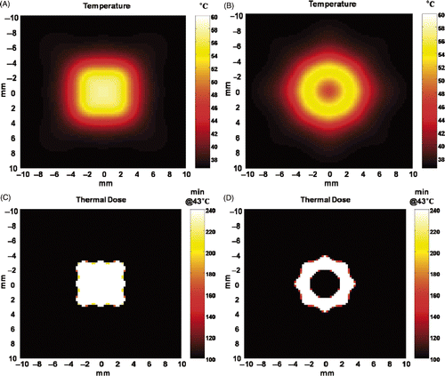
Figure 12. Interference between anti-focus and foci in the axial direction. The intended control values can be obtained when the foci are located approximately 15 mm away from an anti-focus.
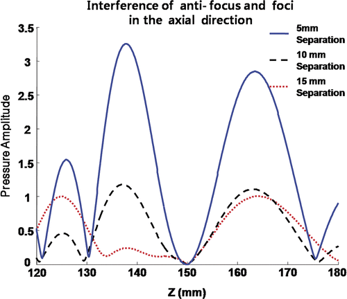
Figure 13. Field simulation of four foci around an anti-focus obtained by iterative weighting. (A) The field after 7 iterations, and (B) the field after 8 iterations, respectively.
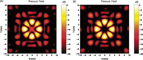
Figure 14. Generation of arbitrary shape field. The field was obtained with the condition of an anti-focus at the (0, 0, 150), a focus at the (3, 0, 15) with the control value of 1, a focus at the (0, 3, 15) with the control value of 0.5, a focus at the (−3, 0, 15) with the control value of 0.3, and a focus at the (0, −3, 15) with the control value of 0.2. Any value between 0 and 1 can be used successfully to create an arbitrary field as necessary.
