Figures & data
Figure 1. Model cross-sections of an elliptical phantom in the single-ring 70-MHz AMC-4 system and two and three-ring waveguide systems at 70 and 130 MHz, respectively.
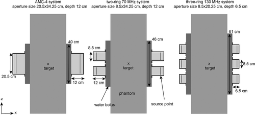
Table I. Modelled waveguide aperture sizes and depths for different operating frequencies.
Table II. Values of the dielectric properties for different tissue types at the frequencies applied in the simulations; conductivity (σ [S m−1]), relative permittivity (εr [-]).
Table III. Values of the thermal properties for different tissue types used in the simulations; density (ρ [kg m−3]), specific heat capacity (c [J kg−1°C−1]), thermal conductivity (k [W m−1°C−1]) and perfusion (Wb [kg m−3s−1]).
Table IV. Values of the Sratio (i.e. the ratio between the maximum SAR in the phantom and the SAR in the central target) for both the homogeneous and the fat-muscle phantom after SAR optimisation. Constraints were set to the output power of each waveguide: an antenna of the single-ring AMC-4 system should deliver at least 10% and at most 40% of the total applied power; for a two-ring system this was at least 5% and at most 25%. For a three-ring system the minimum and maximum output power of each waveguide was constrained to 3% and 15% of the total power, respectively.
Figure 2. Optimised SAR distributions in the homogeneous muscle-equivalent phantom for the 2D single-ring 70 MHz AMC-4 system and 3D double-ring and triple-ring systems at different operating frequencies. Slices were taken in the central xz-plane. For frequencies and configurations for which multiple aperture sizes were simulated, results for the largest aperture size are shown.
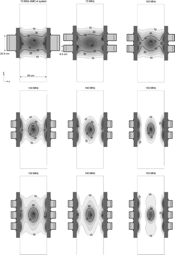
Table V. Optimised indexed tumour temperatures for five cervical cancer patients and the total absorbed power at 70 MHz for aperture sizes 8.5 × 34.25 cm2, 8.5 × 30.25 cm2 and 8.5 × 25.25 cm2. The last column lists the amount of power and the gain in temperature with respect to the single-ring 70-MHz AMC-4 system averaged over the five patients.
Table VI. Optimised indexed tumour temperatures for five cervical cancer patients and the total absorbed power at 100 MHz for aperture sizes 8.5 × 30.25 cm2, 8.5 × 25.25 cm2 and 8.5 × 20.25 cm2. The last column lists the amount of power and the gain in temperature with respect to the single-ring 70-MHz AMC-4 system averaged over the five patients.
Table VII. Optimised indexed tumour temperatures for five cervical cancer patients and the total absorbed power at 120 MHz for aperture sizes 8.5 × 25.25 cm2 and 8.5 × 20.25 cm2. The last column lists the amount of power and the gain in temperature with respect to the single-ring 70-MHz AMC-4 system averaged over the five patients.
Figure 3. Gain in optimised indexed temperatures T10, T50 and T90 (left) with respect to the single-ring 70-MHz AMC-4 system and the corresponding total amount of absorbed power (right) for two-ring waveguide systems at different operating frequencies. Results are averaged over the five patients.
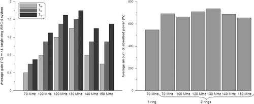
Table VIII. Optimised indexed tumour temperatures for five cervical cancer patients and the total absorbed power using the single-ring AMC-4 system and two-ring waveguide systems at different frequencies. At frequencies for which multiple aperture sizes were simulated, results for the largest aperture size are shown (70 MHz: 8.5 × 34.25 cm2, 100 MHz: 8.5 × 30.25 cm2, 120 MHz: 8.5 × 25.25 cm2). The highest T90 for each patient is written in bold type.
Figure 4. Coronal (top), sagittal (centre) and transversal (bottom) slices of the anatomy of patient 3 (left column). Red corresponds to muscle tissue, fat tissue is yellow, bone is green and inner air is blue. The tumour is represented by the black spot in the centre. The other three columns show the temperature distributions optimised for the 70-MHz AMC-4 system and double-ring systems at 70 and 130 MHz. Left and right of the patient correspond with right and left in these pictures, respectively. The orthogonal slices run through the centre of gravity of the tumour.
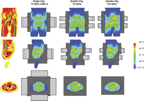
Figure 5. Optimised T90 for each patient simulated with three-ring systems at different operating frequencies. For comparison the optimised T90 with the 70-MHz AMC-4 system and with a two-ring system at 130 MHz (optimum of the two-ring systems) are plotted as well.
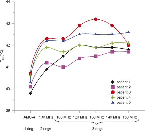
Figure 6. Gain in optimised indexed temperatures T10, T50 and T90 (left) with respect to the single-ring 70-MHz AMC-4 system and the corresponding total amount of absorbed power (right) for three-ring waveguide systems at different operating frequencies. Results are averaged over the five patients. For comparison, the results for the optimal double-ring system at 130 MHz are plotted as well.
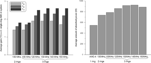
Table IX. Optimised indexed tumour temperatures for five cervical cancer patients and the total absorbed power using three-ring waveguide systems at different frequencies. For reference the optimised results for the single-ring AMC-4 system are repeated here as well as for the optimal frequency for a two-ring system (130 MHz).
Figure 7. Coronal (top), sagittal (centre) and transversal (bottom) slices of the anatomy of patient 1 (left column). Red corresponds to muscle tissue, fat tissue is yellow, bone is green and inner air is blue. The tumour is represented by the black spot in the centre. The other three columns show the temperature distributions optimised for double-ring systems at 70 and 130 MHz and a three-ring system at 130 MHz. Left and right of the patient correspond with right and left in these pictures, respectively. The orthogonal slices run through the centre of gravity of the tumour.
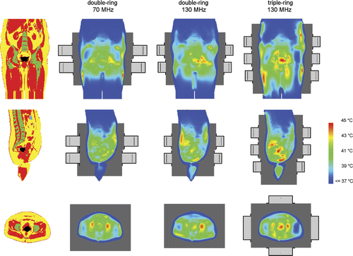
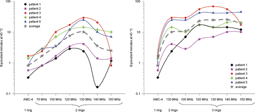
Figure 8. The number of equivalent min at 43°C for the T90 of each patient according to Equation 6 plotted against the operating frequency. The left picture shows the improvement with a two-ring system at higher frequencies and the right picture with a three-ring system. The grey dotted line represents the result for the T90 averaged over all five patients. A log-scale was used on the vertical axis. This graph emphasises the significant improvement in thermal dose delivery that can be achieved by increasing the operating frequency from 70 to 130 MHz.
