Figures & data
Figure 1. (A) The SonoKnife transducer. (B) The housing. The transducer within the acrylic housing can be moved up and down for adjusting the location of the focal plane. Degassed water at 8°C is circulated in the housing to cool the transducer during sonication.
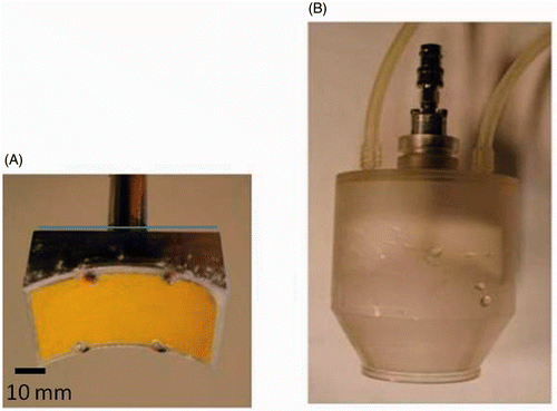
Figure 2. Schematic diagrams of a SonoKnife transducer for the layered medium model. (A) A perspective 3D view. (B) Cross-sectional view (y = 0) showing the water, skin, fat and muscle layers which were used in the simulations. Where R = 60 mm, r = 60 mm, L = 30 mm and d = 30 mm.
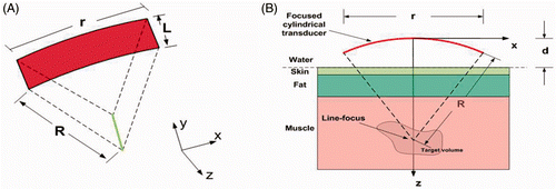
Table I. The acoustic and thermal properties that were used for water, skin, fat and muscle in the simulations, taken from White et al. Citation[19].
Figure 3. The power deposition distribution calculated for the 3.5 MHz transducer in the skin region (at x = 0). The skin surface is at z = 30 mm.
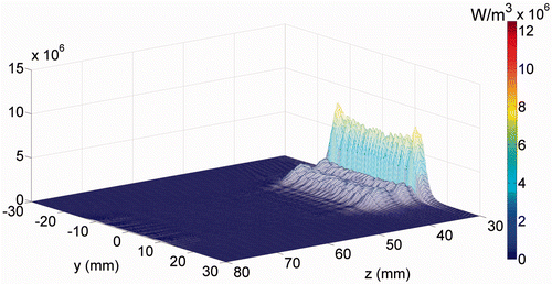
Figure 4. Simulated temperature distribution and thermal dose contours (inner contour > 240 EM 43°C) for the 3.5 MHz transducer, (A) without skin cooling and (B) with skin pre-cooling after 30 seconds of sonication, with transducer emittance of 3 W/cm2. The skin surface is at z = 30 mm. The skin temperature prior to ablation was 8°C. The red and brown arrows point to the predicted ablated regions in the focal plane and skin areas, respectively.
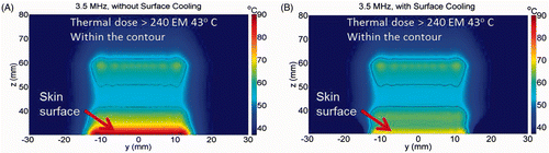
Figure 5. The power deposition distribution calculated for the 1 MHz transducer in the skin region (at x = 0). The skin surface is at z = 30 mm.
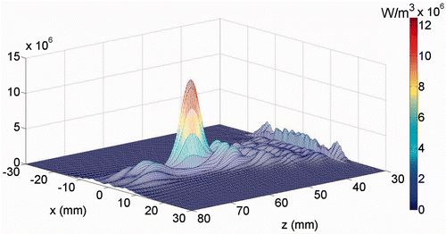
Figure 6. Simulated temperature distribution and thermal dose contours (inner contour > 240EM 43 C) for the 1.0 MHz transducer, (A) without cooling and (B) with skin pre-cooling, after 30 seconds of sonication, with transducer emittance of 3 W/cm2. The skin surface is at z = 30 mm. The skin temperature prior to ablation was 8°C.
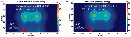
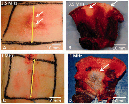
Figure 7. The skin of live pigs after thermal ablation with the SonoKnife using 100 W input power with either 3.5 or 1 MHz transducer for 50 and 300 seconds continuous sonication respectively. Skin cooling was done in both cases by placing an ice pack on the skin surface. The skin temperature was 8°C. (A) Skin burns (pointed with white arrows) seen immediately after ablation with 3.5 MHz SonoKnife transducer. (B) Skin burns in cross section after TTC staining (white arrows point towards the whitish non viable tissue). (C) The skin surface after therapy with 1 MHz SonoKnife transducer, where no skin burns were seen. (D) A subcutaneous thermal lesion is seen in cross section after TTC staining (white arrow points towards the non viable whitish tissue). The yellow double-headed arrow marks the centre of the Sonoknife transducer (along y axis).