Figures & data
Table 1. Influential factors and grouping.
Figure 1. Flow diagram of the registration validation software.
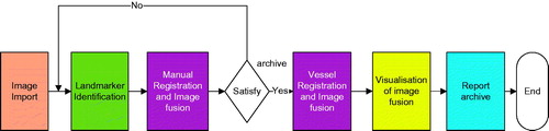
Figure 2. (A–C) Basic 3D ultrasonic images of the anterior right liver lobe in the transverse, coronal and sagittal planes. (D) Vessel tree recognition. (E) Vessel tree segmentation and extraction.
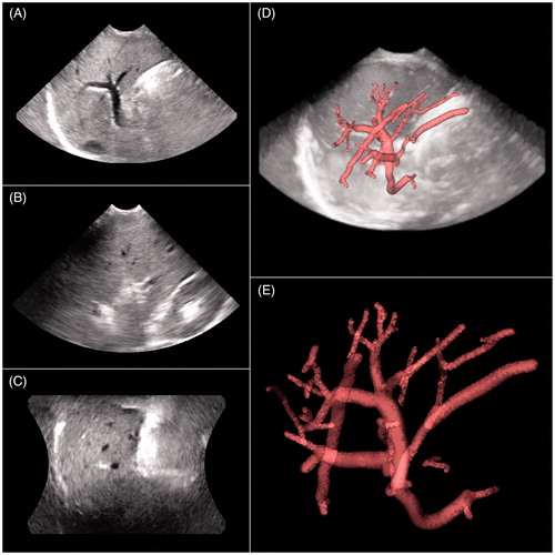
Figure 3. (A) Vessel centre lines recognition in the anterior right liver lobe. (B) Vessel centrelines extraction and bifurcations automatically marked as small spheres.
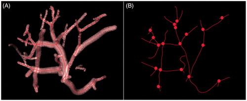
Figure 4. (A, B) Reference image and floating images with vessel centrelines and bifurcation marks, respectively. (C) Registration based on the vessel centrelines; the vessel centrelines of the reference image and the floating images primarily overlapped.
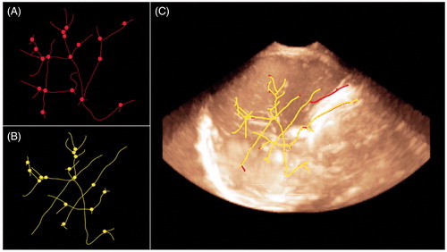
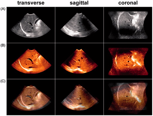
Figure 5. (A) Reference image of the anterior right liver lobe in the transverse, sagittal and coronal planes. (B) Floating image of the anterior right liver lobe in the identical acquisition conditions as A. (C) Fusion image of A and B; the vessel trees of A and B mainly overlapped, and the registration error distance was 1.23 mm. This result indicated that the image fusion of the 3D VT-based automatic registration was successful.
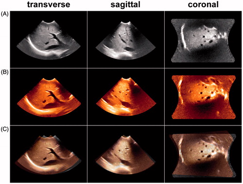
Figure 6. (A) Reference image of the anterior right liver lobe in the transverse, sagittal and coronal planes acquired at end inspiration. (B) Floating image of the anterior right liver lobe acquired at end expiration with the same acquisition conditions as in A. (C) Fusion image of A and B; the vessel trees of A and B did not overlap, and the registration error distance was 14.67 mm. This result indicated that the image fusion of the 3D VT-based automatic registration was a failure.