Figures & data
Figure 1. (A, B) HYPERcollar orientations as used during the treatments. (A) is used for H&N HT group 1, while (B) is used for H&N HT group 2 and 3. The arrows A, B and C are the distances with respect to the applicator ring as currently used in hyperthermia treatment planning. (C) Impact of varying patient positioning on target-to-hotspot quotient (THQ). The error bars represent the minimum and maximum differences in THQ.
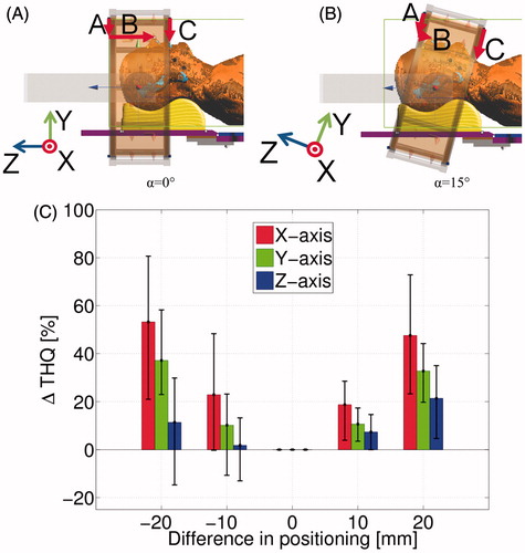
Figure 2. Left: Different water bolus shapes used in the applicator model to investigate the influence on treatment quality. (A) Hyperthermia treatment planning (HTP) shape, (B) HTP with realistic folds (five in total), (C) straight edges, (D) full water background. Right: Influence of water bolus shapes on target-to-hotspot quotient (THQ), compared to the THQ of the standard HTP model.
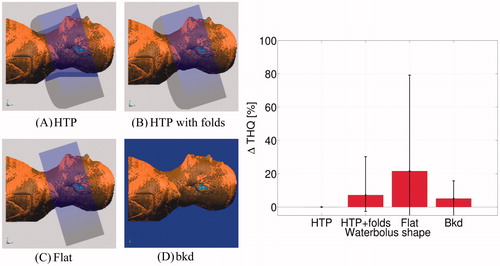
Figure 3. (A, B) Pictures of the small-scale set-up. (C, D) Two examples of CT images of the small-scale set-up. (C) Transversal plane slice in correspondence with the middle position of the water bolus shell. (D) Coronal plane slice in correspondence with the applicator horizontal axis. (E) Picture taken through the cavity in the wooden plate to evaluate the water bolus contact from the inside of the mould. The blue part is the inner water bolus. (F) IR picture taken from the same position as (E), showing the temperature distribution of the water bolus through the plastic head-conformal mould.Left side view of the small-scale setup. 1: Wooden plate; 2: Morphologic transparent surface model of a human; 3: Hard-plastic rigid WB holding the inner WB; 4. Tubing for the inflow and outflow of cooled water of the inner WB; 5: Iron glider to shift the WB over as it would be in the applicator redesign.
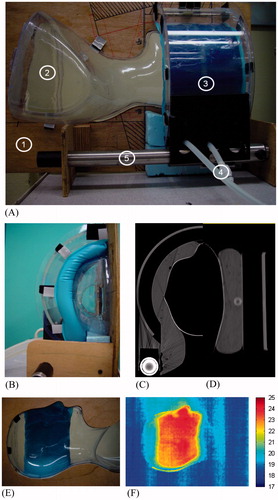
Figure 4. (A) Artist’s impression of the new applicator design and positioning procedure. The patient is initially placed on the treatment bed, with a rough indication of the position for the hips (2) before lowering the upper body. Positioning the H&N on the headrest (HR) (3) is assisted by a middle-sagittal laser-line (4) for aligning the patient. The laser line (5) is used to measure the head rotation, and to adapt the position of the HR accordingly, to set the head rotation such that it matches the head rotation in the hyperthermia treatment planning CT-scan. Second, the two applicator shells (6) slide on the gliders (7) over the patient’s head to the intended position. The shells are then closed, such that they form a cylindrical shape by rotating the shells on the gliders. Finally, the water boluses are filled with water, thereby filling the space between the patient and the outer water boluses. (B) New positioning strategy, showing the distances A and B with respect to a fixed reference point (P2) on the redesigned applicator. The angle β is the angle of a line through the philtrum and the most cranial part of the left ear (P1), with respect to the horizontal plane. The angle β is derived from the radiotherapy CT-scan, while A and B are derived from a test positioning procedure with the patient.
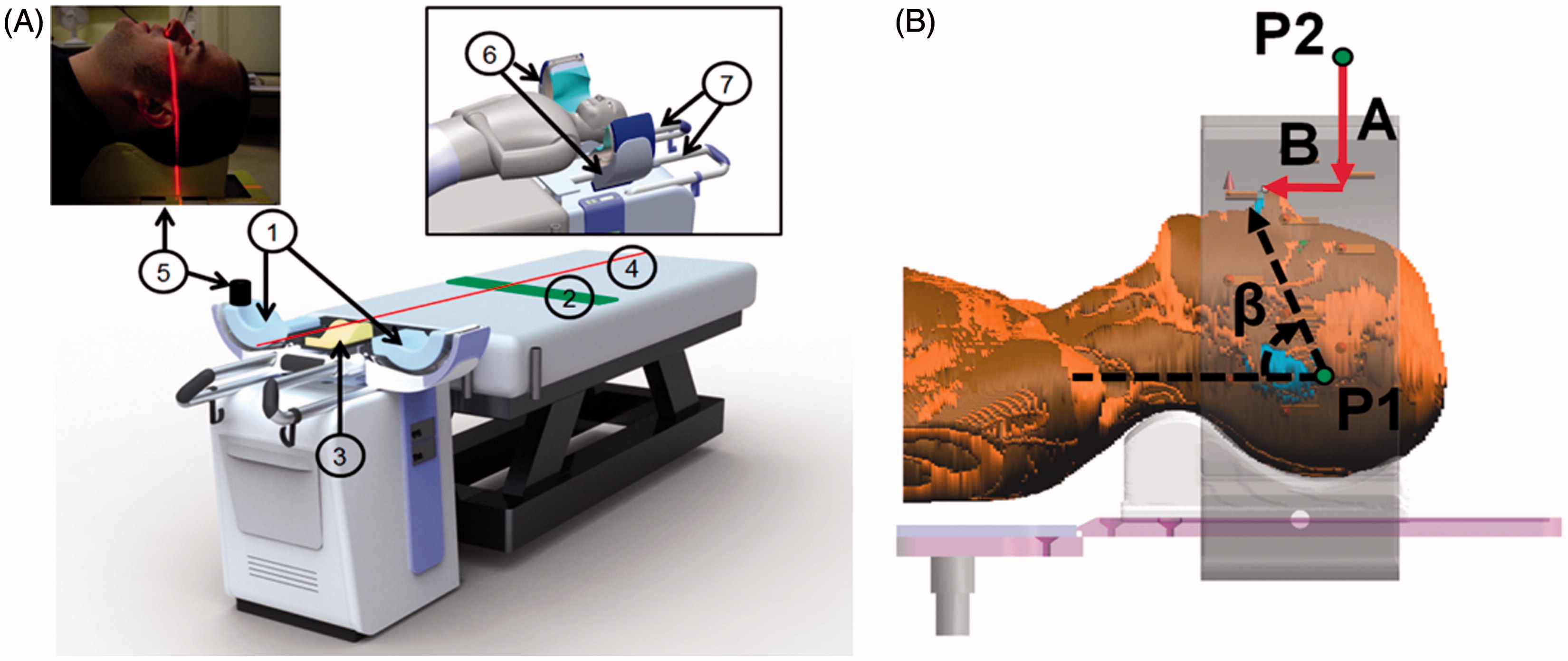
Figure 5. Patient in the HYPERcollar. Folds can be seen in the water bolus on both sides of the patient. The red arrows emphasise the folds that divide the water boluses into different sections and thereby block the water circulation. Also note the sticky tape that is used to create an air cavity for breathing.
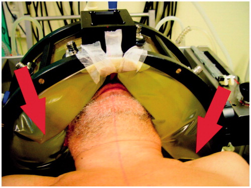
Figure 6. Proposal of the new inner water bolus design. (1) Open cell, water-permeable polypropylene foam insert, surrounded by a non-elastic foil (2). The foam insert should ensure a predictable shape after filling, since the elastic styrene ethylene butylene styrene (SEBS)-foil (3) exactly fits the foam, and during filling the water bolus will mostly expand in the direction of the patient’s skin and not to the sides. Water tubes (4) are inserted for water circulation and hence, temperature homogeneity.
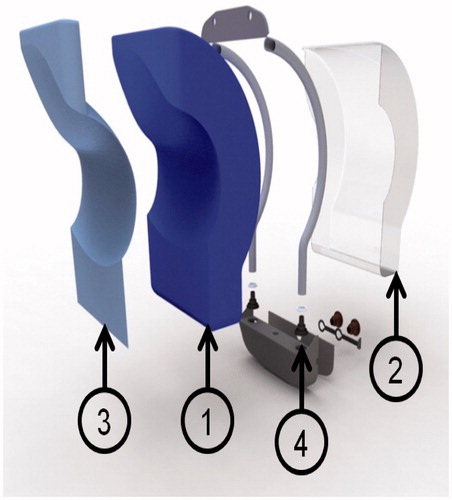
Figure 7. The redesigned applicator under construction. The volunteer test was carried out early in the construction phase to allow for modifications if the new positioning procedure was inadequate.
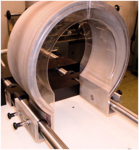
Figure 8. Results from the positioning test with volunteers, showing the difference between the position of the volunteer before and after the 5 min of lying in the redesigned applicator.
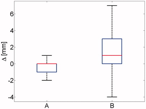
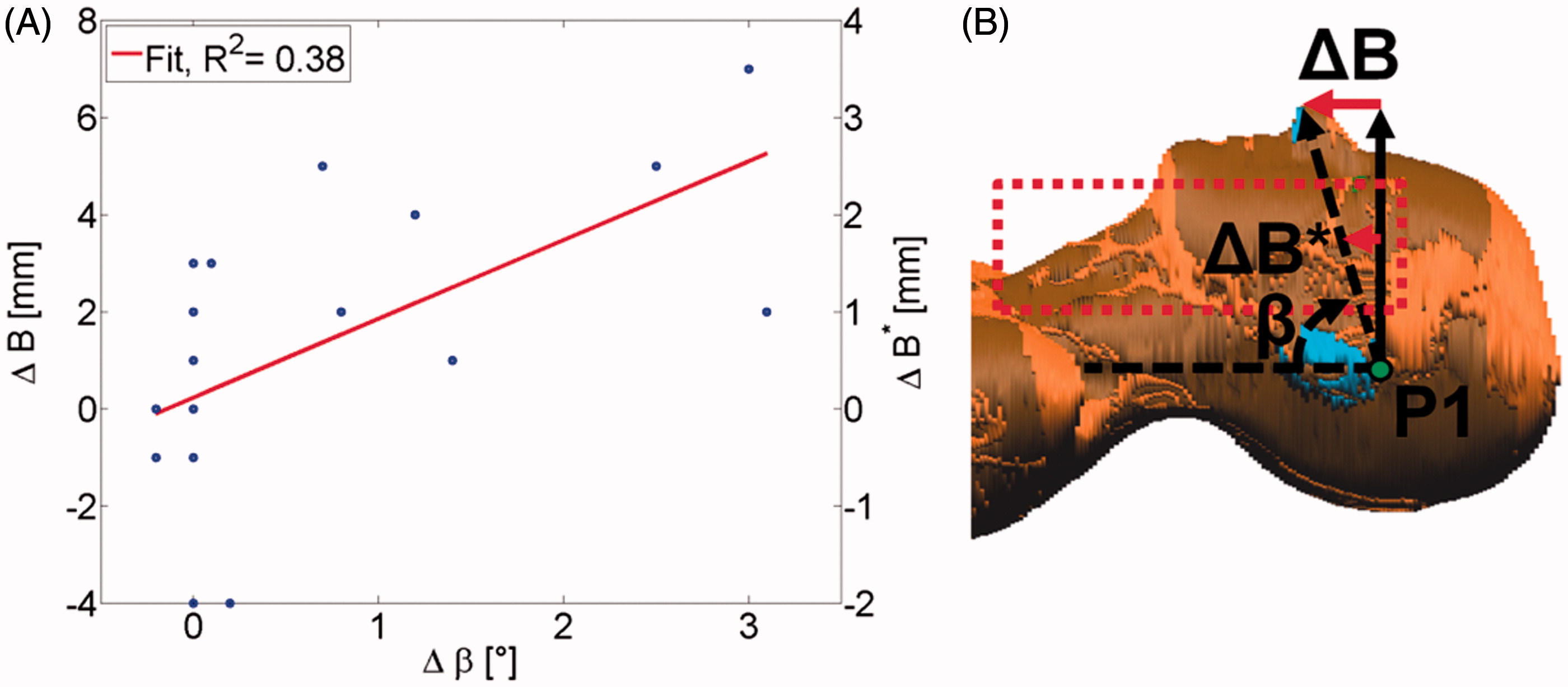
Figure 9. (A) Correlation of δβ and PB which shows that the largest values of δB are for the largest part caused by rotation of the patient (δβ) and not by a shift of the patient. (B) Explanation of δB*. Assume that the patient is rotated around the axis through P1, causing a shift in the measured B. The tumours of H&N patients are mostly located in the area indicated by the dotted rectangle. Because the target region is closer (roughly twice on average) to the point of rotation (P1) than the point of the nose where B is measured, we assume the shift of the tumours to be δB* = 1/2*δB.