Figures & data
Figure 1. Four kinds of phase shift ablation modes (PsM-45°, PsM-90°, PsM-135°and PsM-180°) with a phase shift angle range of 45–180° in 45° step sizes.
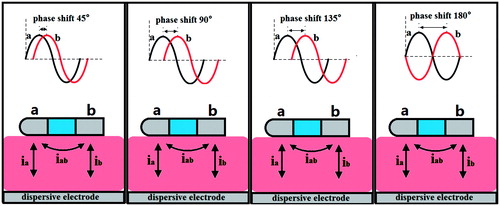
Figure 2. The geometry of the computational model (not to scale). The thickness of the atrial wall is 5 mm. Electrode diameter D = 2.31 mm (7 Fr), electrode length L = 4 mm, insertion depth 0.5 mm and electrode spacing 4 mm.
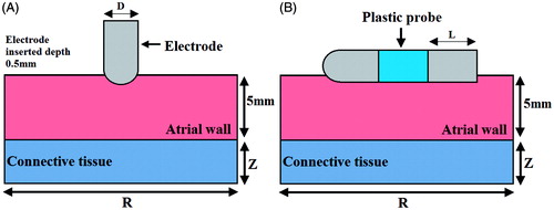
Table 1. Thermal and electrical characteristics of the elements of the numerical models.
Figure 3. Electrical and thermal boundary conditions of the models: (A) phase shift mode, (B) bipolar mode and (C) unipolar mode.
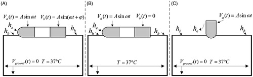
Figure 4. Temperature distribution in the tissue after 60 s of RF ablation across 5 mm wall thickness and 4 mm catheter spacing, considering three modes of ablation: (A) unipolar mode, (B) bipolar mode, and (C∼F) phase shift angle ablation PsM-45°, PsM-90°, PsM-135°, PsM-180°. The solid black line is the thermal damage border.
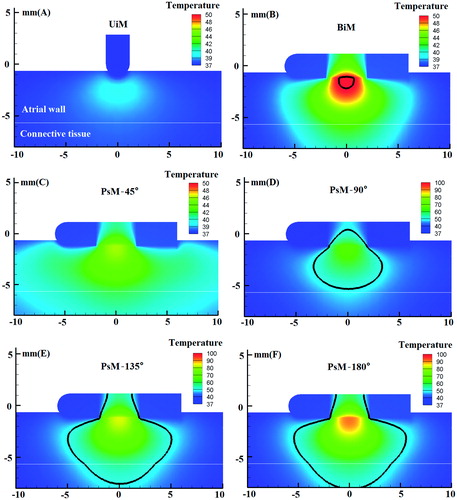
Table 2. Lesion dimensions for three modes of RF ablation: PsM mode, BiM mode and UiM mode.
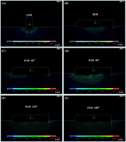
Figure 5. Current density distribution in the tissue considering three modes of ablation UiM, BiM and PsM.