Figures & data
Figure 1. The two methods to spread the beam in the transverse plane: scattering (left) and pencil beam scanning (right).
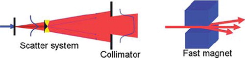
Figure 2. In the “step and shoot” method of pencil beam scanning the beam is aimed at sequential volume elements. When continuous scanning is used, the beam is swept along a contour or a line, while varying the beam intensity.
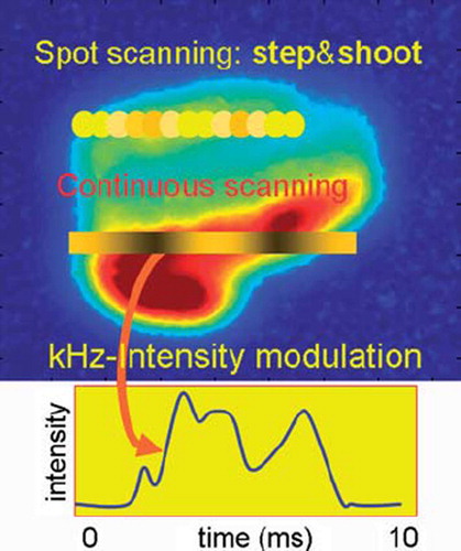
Figure 3. With a fast acting electrostatic deflector plate in the center of the cyclotron the beam can be deflected and partially intercepted by a vertical limiting collimator. The voltage on the plates is used to regulate the beam intensity extracted from the cyclotron [Citation23].
![Figure 3. With a fast acting electrostatic deflector plate in the center of the cyclotron the beam can be deflected and partially intercepted by a vertical limiting collimator. The voltage on the plates is used to regulate the beam intensity extracted from the cyclotron [Citation23].](/cms/asset/ee4c5f05-9a3f-4a1c-a7b1-1ae212d1ceaf/ionc_a_582513_f0003_b.jpg)
Figure 4. Compact cyclotron systems from Still River Systems (left) and IBA (right), allowing a proton therapy machine in a single treatment room [Citation28,Citation29].
![Figure 4. Compact cyclotron systems from Still River Systems (left) and IBA (right), allowing a proton therapy machine in a single treatment room [Citation28,Citation29].](/cms/asset/2eb24648-a191-4264-afe8-94450b605d4b/ionc_a_582513_f0004_b.jpg)
Figure 5. Principle of operation of the Dielectric Wall Accelerator [Citation42]. A traveling high gradient field is created by switching high voltages on electrodes that are sandwiched between High Gradient Insulators.
![Figure 5. Principle of operation of the Dielectric Wall Accelerator [Citation42]. A traveling high gradient field is created by switching high voltages on electrodes that are sandwiched between High Gradient Insulators.](/cms/asset/fad7f4e9-751c-47f3-aa21-732cfc14a653/ionc_a_582513_f0005_b.jpg)
Figure 6. A laser driven accelerator is based on a high power laser pulse, impinging on a target doped with hydrogen atoms. The laser light accelerates the electrons out of the foil, so that an electric field is created that pulls out protons from the foil.
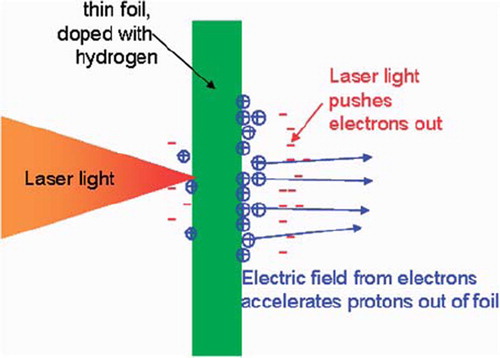
Figure 7. The deflection of a proton beam in a magnetic field, typical for a MRI.
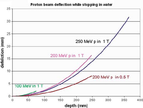
Figure 8. A proton radiograph of a phantom of the head [Citation58].
![Figure 8. A proton radiograph of a phantom of the head [Citation58].](/cms/asset/4a0499a6-7b06-4e21-a4e4-e3e0072fea71/ionc_a_582513_f0008_b.jpg)
Figure 9. The lateral beam size (sigma) of proton beams of different energies as a function of depth in water. When entering the water the beam size has a Gaussian shape with a standard deviation (sigma) of 1 mm. The “virtual” standard deviations of photon beams from a “Gamma knife” and of a “Cyber knife” are indicated as black dots. These are derived from published penumbra data of photon beams [Citation64,Citation65]. The typical width of these beams is about 4 mm and indicated with the dashed vertical arrow.
![Figure 9. The lateral beam size (sigma) of proton beams of different energies as a function of depth in water. When entering the water the beam size has a Gaussian shape with a standard deviation (sigma) of 1 mm. The “virtual” standard deviations of photon beams from a “Gamma knife” and of a “Cyber knife” are indicated as black dots. These are derived from published penumbra data of photon beams [Citation64,Citation65]. The typical width of these beams is about 4 mm and indicated with the dashed vertical arrow.](/cms/asset/1d482c51-4631-438f-83bb-5191854a3e47/ionc_a_582513_f0009_b.jpg)
Figure 10. A possible layout of a proton therapy system using a continuous high intensity beam, which is split at septum magnets following defocusing quadrupole magnets. Kicker magnets controlling beam on/off and intensity per gantry room are indicated with “k”. Each treatment room has its own degrader and beam analysis system (“Energy Selection System”, ESS, possibly to be included in the gantry optics). This method allows complete independence of the treatment rooms with respect to each other. In this respect the experience until 2005 at PSI has shown that a safe patient treatment operation is possible with a beam that has been split off from 2 mA proton beam of 590 MeV [Citation3].
![Figure 10. A possible layout of a proton therapy system using a continuous high intensity beam, which is split at septum magnets following defocusing quadrupole magnets. Kicker magnets controlling beam on/off and intensity per gantry room are indicated with “k”. Each treatment room has its own degrader and beam analysis system (“Energy Selection System”, ESS, possibly to be included in the gantry optics). This method allows complete independence of the treatment rooms with respect to each other. In this respect the experience until 2005 at PSI has shown that a safe patient treatment operation is possible with a beam that has been split off from 2 mA proton beam of 590 MeV [Citation3].](/cms/asset/9eefdada-a2e1-459a-a386-f66e0c0ffcc5/ionc_a_582513_f0010_b.jpg)