Figures & data
Table I. Dose planning specific parameters: prescribed dose to the PTV (Gy), PTV volume (cm3), parotid gland volume (cm3), overlap between the parotid gland volume and the PTV (cm3, %).
Table II. Machine specific parameters: minimum segment size (cm3) in OMP, smoothing parameters (x,y) in Eclipse, number of monitor units, MU with and without GAO in Eclipse and OMP, and the decrease in number of monitor units, MU, (%) by using GAO in both Eclipse and OMP.
Figure 1. The average absorbed dose (Gy) to the parotid gland, <D>parotid gland, in the trade-off as a function of the under-dosage to the PTV, VPTV,D < 95%, with equidistant beam geometry and GAO in Eclipse and OMP.
Figure 2. The average absorbed dose (Gy) to the parotid gland, <D>parotid gland, in the trade-off as a function of the dose homogeneity (D5-D95) in the PTV.
Table III. The number of treatment plans generated with and without GAO in Eclipse and OMP.
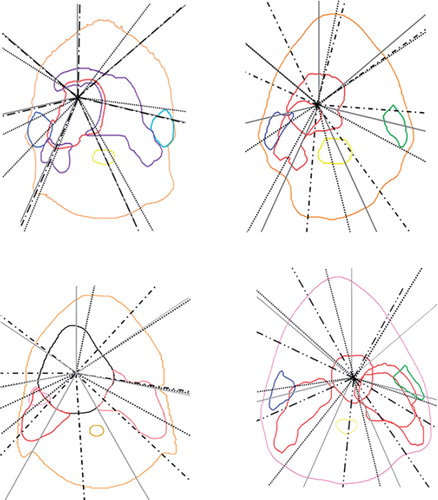
Figure 3. The beam geometries obtained using GAO in the OMP system (black dots), in the Eclipse system (black dashed lines) and the equidistant beam geometry (grey solid lines) for the four cases calculated as average beam geometries for all treatment plans generated. The colours for the ipsilateral parotid/PTV in the trade-off are for Case 1 (upper left) blue/ red, Case 2 (upper right) blue/red, Case 3 (lower left) pink/red and Case 4 (lower right) green/red.