Figures & data
Figure 1. Time line of the entire treatment course including the planning 4DCT scan, daily setup CBCT scans, and the second 4DCT scan acquired approximately at fraction 14.
Table I. Absolute differences in CTV-t mean doses between CT1 and CT2 and between CT1 and CT1 including target motion. Similarly for CT2 and CT2 including target motion.
Figure 2. Dosimetric impact of anatomy changes and target motion for all 16 patients. For each patient, the six columns show the mean CTV-t dose for the original static treatment plan in CT1 (column 1), for the same plan with addition of respiratory motion (column 2) and interfraction baseline shifts (column 3), as well as for the treatment plan transferred to CT2 and calculated without motion (column 4) and with respiratory motion (column 5) and interfraction baseline shifts (column 6).
Figure 3. Examples of anatomical changes from the planning 4DCT scan (CT1) to the 4DCT scan (CT2). GTV-t is contoured in red and CTV-t is contoured in pink. Upper panel: Sagittal view of Patient 5 illustrating tumor shrinkage in CT2, and (right) dose volume histograms (DVHs) showing the resulting impact on the CTV-t dose. Lower panel: Transversal CT slices of Patient 10 treated with post-operative RT, illustrating pleural effusion in CT2, and DVHs for CTV-t.
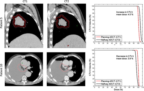
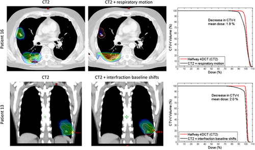
Figure 4. Examples of tumor motion. The GTV-t is contoured in red and CTV-t is contoured in pink. The dose distribution is shown as dose color wash with a minimum dose shown at 95%, and a maximum dose at 107%. Upper: transversal CT slice of Patient 16 at CT2 without and with inclusion of respiratory tumor motion. Lower: Coronal view of Patient 13 at CT2 without and with inclusion of interfraction baseline shifts. The corresponding CTV-t DVHs are shown to the right.