Figures & data
Figure 1. Asymmetrical structures are susceptible to external forces (upper row). A building lacking part of its structure (above right) is expected to yield to less force than its intact counterpart (above left). Similarly, skulls with unilateral complete cleft palate are expected to be more susceptible to fractures than intact skulls (lower row).
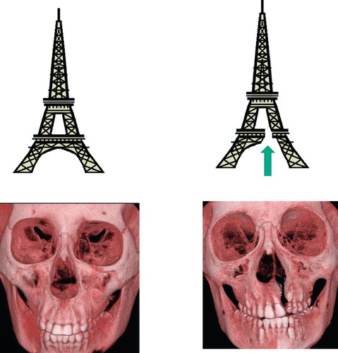
Figure 2. The experimental device used for the actual study. (Left) Each skull is fixed and placed under a stainless steel pipe. (Right above) The pipe is placed so that its lower end matches the inferior orbital rim. (Right below) The brass weight slides inside the pipe and strikes the inferior orbital rim.
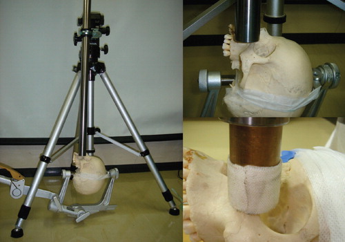
Figure 3. (Above left) Skulls with no deformity were included in the intact skull group. (Above right) Skulls in which the anterior part of the maxilla and hard palate were removed were included in the cleft skull group. (Lower row) Fractures occurring in the two models shown in the upper row. The areas enclosed by the fracture lines were defined as actual fracture areas (marked with arrows), and were measured for each model.
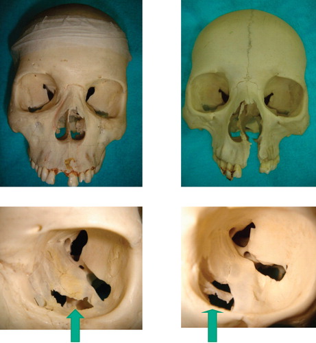
Table I. Material properties used for analysis.
Figure 4. Representative models designed by computer viewed from different angles for the intact model group (left column) and cleft model group (right column), respectively.
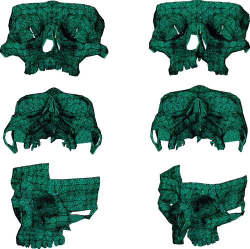
Figure 5. Traumatic energy equivalent to 1.8 J was applied on the inferior orbital rims of the computed models of the intact model group (left column) and cleft model group (right column).
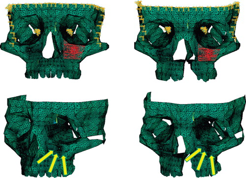
Figure 6. Sites of the three marking points at which deviation was evaluated. IOR=inferior orbital rim; RPM=rim of the pyriform margin; and AWM=anterior wall of the maxilla.
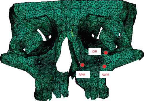
Table II. Actual fracture areas (mm2) (n = 8 in each group).
Figure 7. Representative patterns of the theoretical fracture areas (the areas of the regions where the stresses exceed the yield criterion of the bone: marked with red) for the intact model group (left column) and the cleft model group (right column), respectively.
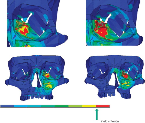
Figure 8. Representative patterns of maxillary deviation for the intact model group (left column) and cleft model group (right column), respectively. The maxilla deviates more in the cleft model group than in the intact model group.
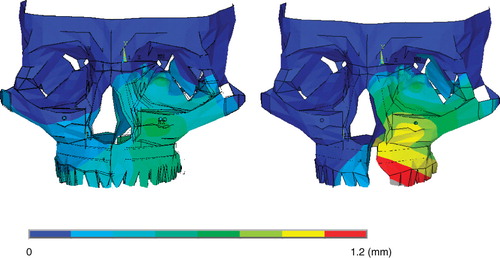
Table III. Theoretical fracture areas (mm2) (n = 12 in each group).
Table IV. Deviations of the marking points on impact (mm).
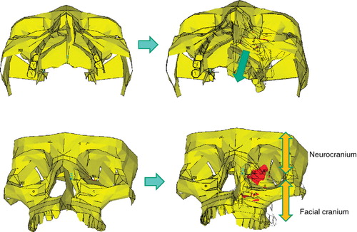
Figure 9. In patients with cleft palate, the maxilla on the cleft side deviates in the posterior direction when impacts are applied (from left column to right column). The orbital walls constitute a junction between the facial cranium and the neurocranium (right below). Intensified stresses therefore occur on the orbital walls as the maxilla on the cleft side moves posteriorly (red regions).