Figures & data
Table I. Historical development of rapid prototyping and relevant medical uses (Citation24,Citation28–31).
Figure 1. RP process chain showing main process steps. Adapted from reference (Citation48) with permission of Rapid Prototyping Journal, Emerald, Copyright 2009.
Figure 2. Overview of RP technologies. Adapted from reference (Citation50) with permission of Macromolecular Materials and Engineering, John Wiley and Sons, Copyright 2008.
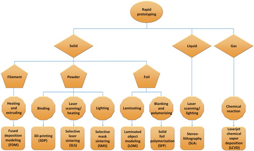
Figure 3. Schematic of two types of SLA setups. (A) A bottom-up system with a scanning laser. (B) A top-down setup with digital light projection (DLP). DLP is a method to illuminate the resin. A 2D pixel pattern is projected onto the coated glass plate with a digital mirror device (DMD), and then a complete resin is cured immediately. Adapted from reference (Citation54) with permission of UTpublications, University of Twente, Copyright 2010.
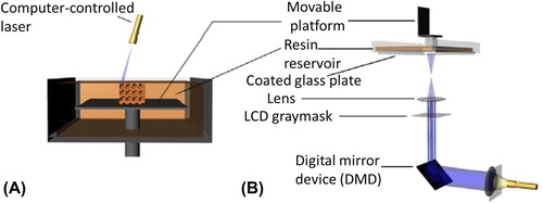
Figure 4. Schematic of the SLS technology. Adapted from reference (Citation48) with permission of Rapid Prototyping Journal, Emerald, Copyright 2009.
Figure 5. Schematic of the FDM technology. Adapted from reference (Citation70) with permission of Biomaterials, Elsevier, Copyright 2002.
Figure 6. Schematic of the LOM technology. (A) Heating. (B) Bonding. Adapted from reference (Citation72) with permission of Manufacturing Practices, Indian Institute of Technology Delhi, Copyright 2012.
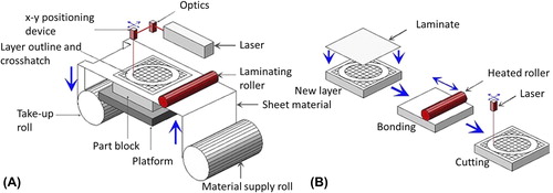
Figure 7. Schematic of the 3DP technology. Adapted from reference (Citation48) with permission of Rapid Prototyping Journal, Emerald, Copyright 2009.
Table II. Comparison of selected RP technologies (Citation48–52,Citation74–77).
Figure 8. (A) Precontoured mandibular reconstruction plate placing over the right mandible with ameloblastoma, (B) Reconstruction plate bridging the gap following tumor resection. Adapted from reference (Citation15) with permission of Oral Surgery, Oral Medicine, Oral Pathology, Oral Radiology, and Endodontology, Elsevier, Copyright 2009.
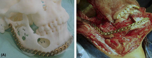
Figure 9. (A) General view of the implant-bearing skull. Implants are fixed with miniplates for mandibular defect. (B) The drill holes for screw insertion were made after positioning of the implants using a common bone drill. Adapted from reference (Citation157) with permission of Journal of Cranio-Maxillofacial Surgery, Elsevier, Copyright 2010.
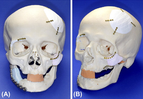
Figure 10. Preoperative planning for patients with craniomaxillofacial post-traumatic deformity. (A) Resinous craniofacial model manufactured using a rapid prototyping device. (B) Preshaping of titanium mesh or plates on rapid prototyping models. (C) Preoperative view of the patient. (D) Postoperative view of the patient. (E) Preoperative mouth opening of the patient. (F) Postoperative mouth opening of the patient. (G) Preoperative occlusion. (H) Postoperative occlusion. Adapted from reference (Citation162) with permission of Journal of Oral and Maxillofacial Surgery, Elsevier, Copyright 2014.
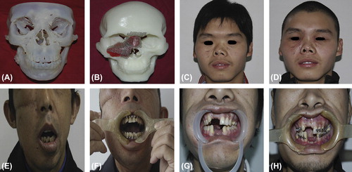
Figure 11. (A) Appearance of face before treatment of left side blowout orbital fracture where lowered left eyeball, restricted upward movement, and narrowed palpebral fissure are observed. (B) Computer tomography image of the left orbit with sagittal plane reconstruction with arrow indicating the damaged orbital floor. (C) Physical (solid) model of left orbital floor with formed titanium mesh. Adapted from reference (Citation173) with permission of Journal of Cranio-Maxillofacial Surgery, Elsevier, Copyright 2009.
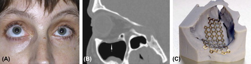
Figure 12. (A) Preoperative view. (B) Computer-aided design. The unaffected right mandible was mirrored to the left (red). The discrepancy between the mirrored right mandible and the native left mandible (green) was extracted (blue). For additional compensation of the atrophied soft tissue, the outer surface was expanded by 1.5 mm. (C) Postoperative view with the facial symmetry reconstructed. Adapted from reference (Citation169) with permission of British Journal of Oral and Maxillofacial Surgery, Elsevier, Copyright 2009.
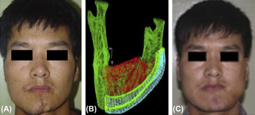
Figure 13. (A) Patient's preoperative frontal view. (B) Frontal view of centric occlusion with transverse maxillary cant and maxilla midline deviation. (C) Preoperative 3D model reconstructed based on CT scanning. (D) Postoperative frontal view: the patient's maxillary transverse cant and midline deviation were corrected as the preoperative surgical design. (E) Postoperative 3D model reconstructed based on CT scanning. Adapted from reference (Citation192) with permission of Oral Surgery, Oral Medicine, Oral Pathology, Oral Radiology, and Endodontology, Elsevier, Copyright 2010.
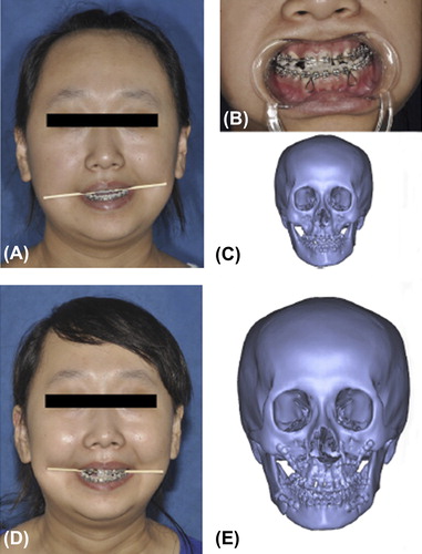
Figure 14. (A) Initial facial view. (B) Initial facial smiling. (C) Pretreatment intraoral photograph. (D) Final facial view. (E) Final facial smiling. (F) Final intraoral photograph. Adapted from reference (Citation231) with permission of Head and Face Medicine, BioMed Central, Copyright 2014.
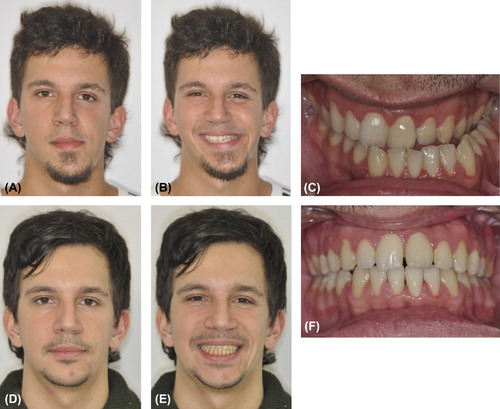
Figure 15. (A) Picture of patient taken with 3dMDfaceTM. (B) Color model made with the ZPrinter® 450 (Z Corporation, Burlington, MA) and a high performance composite material. (C) Clay sculpture on model. (D) Patient with final prosthesis and glasses. Adapted from reference (Citation238) with permission of Journal of Prosthodontics, John Wiley and Sons, Copyright 2011.
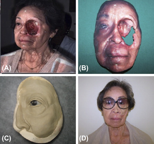
Figure 16. (A) Patient with facial malformation. (B) A margin 2 mm wide was measured and cut. (C) A layer of the virtual preliminary prostheses 0.5 mm thick was subtracted (a) and the subtracted layer of 0.5 mm magnified (b). (D) Rapid prototype wax prosthesis. (E) Finished wax prosthesis with surface texture, follicular orifices, and adaptable margin. (F) Patient with final silicone prosthesis. Adapted from reference (Citation239) with permission of British Journal of Oral and Maxillofacial Surgery, Elsevier, Copyright 2010.
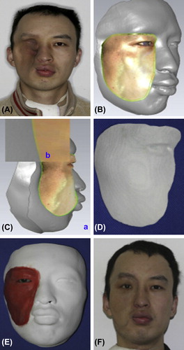
Figure 17. (A) Initial appearance of patient's face with injury from accidental gunshot. (B) Final prosthesis on patient. Adapted from reference (Citation41) with permission of Journal of Rehabilitation Research and Development, U.S. Department of Veterans Affairs, Copyright 2010.
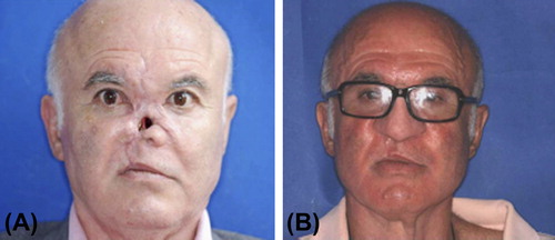
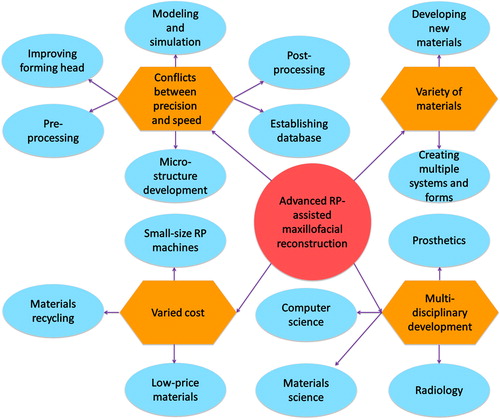
Figure 18. Solutions for technical challenges faced by advanced RP-assisted maxillofacial reconstruction.