Figures & data
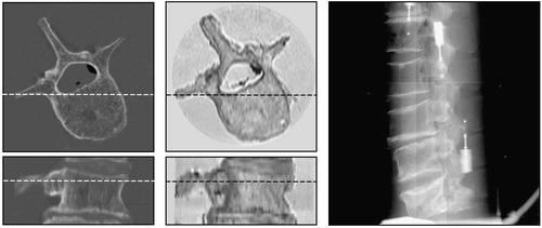
Figure 1. The spine fastened in a plastic tube (top left); the final phantom with fiducial markers attached to the outside of the tube (bottom left); CT image (top center); MR image (top right); and AP (bottom center) and lateral (bottom right) X-ray images of the phantom.
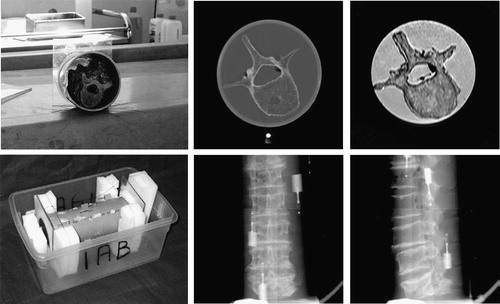
Figure 2. X-ray image acquisition.
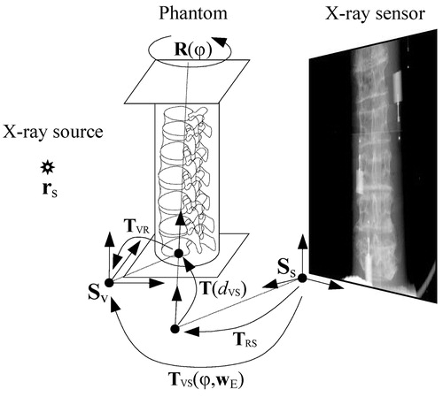
Figure 3. Close-up views of fiducial markers in CT (left), MR (center) and X-ray (right) images.
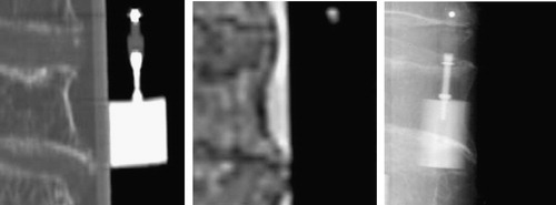
Figure 4. Reconstruction of 3D marker position. Due to the uncertainty of X-ray marker localization and X-ray setup calibration, the projection lines do not cross at the same point.
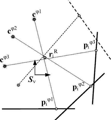
Table I. Expected RMS TREs for “gold standard” registration (in mm).
Figure 5. Transverse and sagittal views of CT (left) and MR (center) sub-volumes, and a lateral X-ray image (right).