Figures & data
Figure 1. The spine frame (1) is mounted on the operating table and fixes the bony structures of the spine cadaver in a rigid position via the spinal processes. In front, the Bronze Millenium Arm (2) system (Faro, Stuttgart, Germany) for three-dimensional measurement is shown.
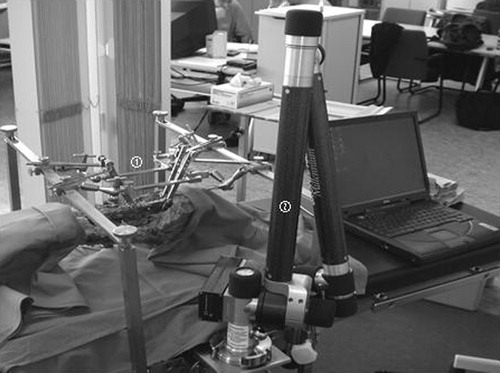
Figure 2. The spine frame includes a soft tissue retractor (1; Ulrich, Germany) that is fixed by four adjustable joint arms (2) to the horizontal rods (3) of the frame. The fixation of the spine is provided by a clamp (4) directly mounted on the spinal processes and linked by titanium arms (5) to the frame.
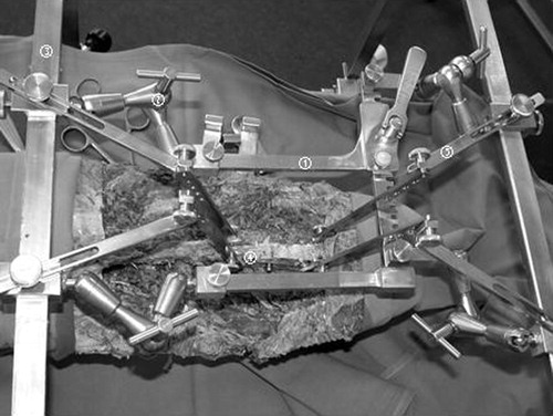
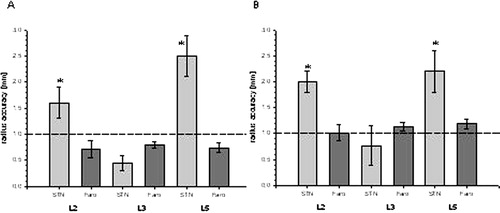
Figure 3. The radii of deviation of each segment following pedicle screw insertion at L3 (a) and controlled lateral traction (b) compared with baseline positions are shown as bar diagrams. The deviation of reference markers measured by the Faro arm (light bars) is lower or merely 1 mm in all segments following both procedures. Measurements using the navigation system (dark bars) show adequately low deviations in the registered L3 segment after both manipulations. Deviations in the neighboring segments are significantly higher according to the system- and registration-related inaccuracy (results are given as mean ± standard error of the mean, *p < 0.01).