Figures & data
Figure 1. Problems of preoperative-CT- and intraoperative-fluoroscopy-based CAOS systems.
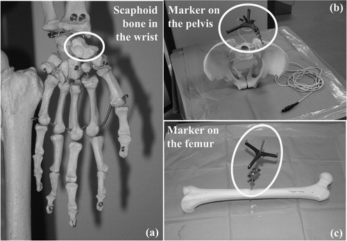
Figure 2. An overview of the methodology of the proposed UCAOS system.
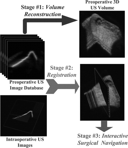
Figure 3. Object-oriented component-based system design in UML.
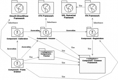
Figure 4. Hardware configurations of the proposed UCAOS system.
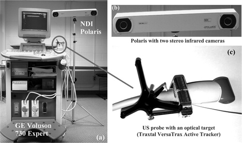
Figure 5. Experimental setup. (a) A stainless steel mounting jig was built to image a radius-bone phantom in a water bath. (b) A wooden mounting brace was wrapped around the arm of a human subject using velcro pads.
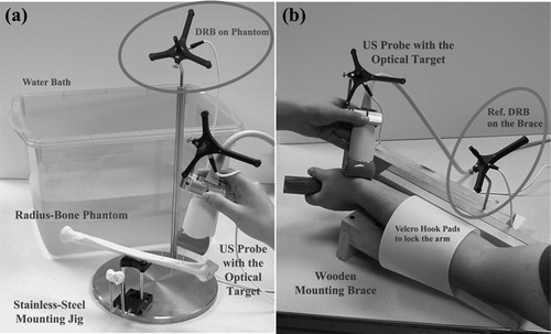
Figure 6. (a) The N-wire US probe calibration phantom. (b) A US image showing the cross-section of the N-wires.
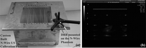
Figure 7. Validation of the US probe calibration result.
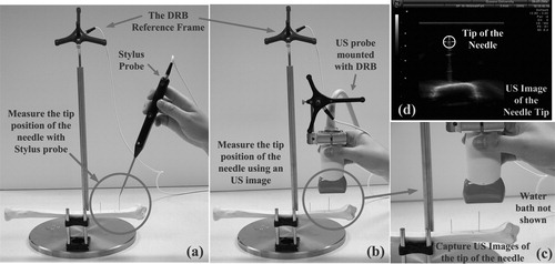
Table 1. Validation of the US probe calibration result.
Figure 8. 3D US volume reconstruction process.
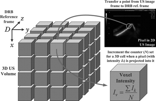
Figure 9. 3D US volume rendering of the distal end of a radius-bone phantom.
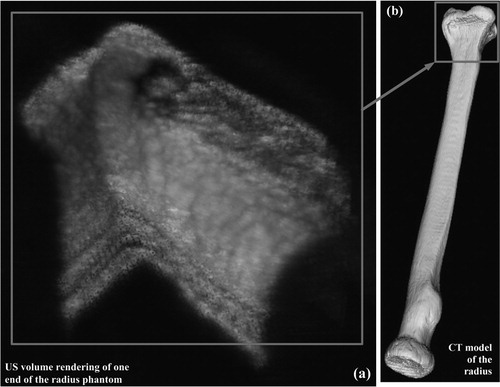
Figure 10. Registration results of Experiment Type I with live images randomly selected from the preoperative images: best matching results for one of the live images from the radius phantom (a and b) and the human subject (c and d) (color version available online).
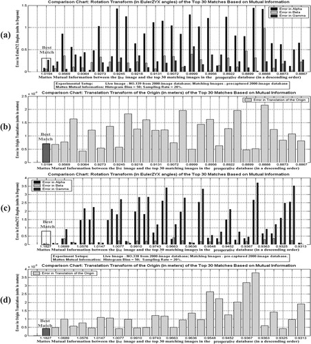
Figure 11. Registration results of Experiment Type II with live images acquired at a different time: best matching results for one of the live images from the human subject (a and b) (color version available online).
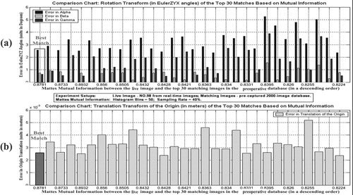
Figure 12. Visualization of the registration result (color version available online).
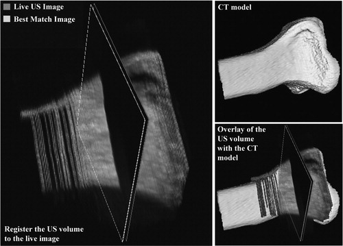
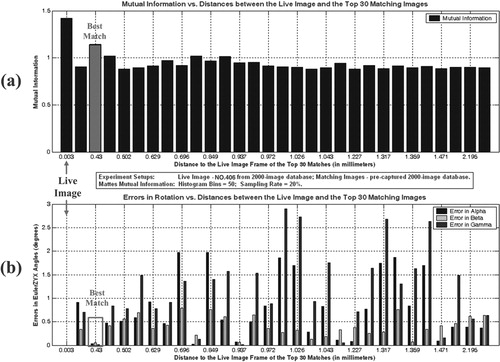
Figure 13. Relationship between the mutual information and the distance of the matching images to the live image (color version available online).