807
Views
3
CrossRef citations to date
0
Altmetric
Biomedical Paper

Real-time tracking of vertebral body movement with implantable reference microsensors

, , , , &
Pages 137-146 | Received 11 Jan 2006, Accepted 14 Mar 2006, Published online: 06 Jan 2010

Figures & data

Figure 1. It is wrongly assumed that a force acting locally spreads evenly over several segments of the spine.
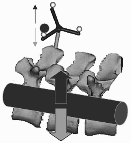
Figure 1. It is wrongly assumed that a force acting locally spreads evenly over several segments of the spine.

Figure 2. The microsensors have a diameter of approximately 1.8 mm and a length of approximately 8.4 mm including the sterilizable capsule.
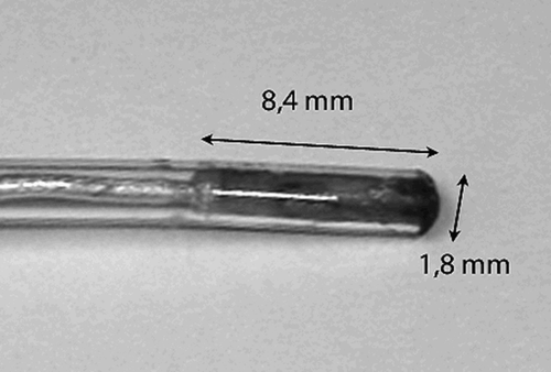
Figure 2. The microsensors have a diameter of approximately 1.8 mm and a length of approximately 8.4 mm including the sterilizable capsule.

Figure 3. (a) 3D segmented vertebral body with landmarks for point-to-point registration. (b and c) Vertebral body model (c) and 3D segmented model (b) during position error (PE) measurements along the sagittal axis.
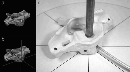
Figure 3. (a) 3D segmented vertebral body with landmarks for point-to-point registration. (b and c) Vertebral body model (c) and 3D segmented model (b) during position error (PE) measurements along the sagittal axis.

Figure 4. Computed 3D reconstruction before (c) and after (d) simulated cage-fusion C6/7 compared with a digital photograph of the pre- and post-interventional spine model (a and b).
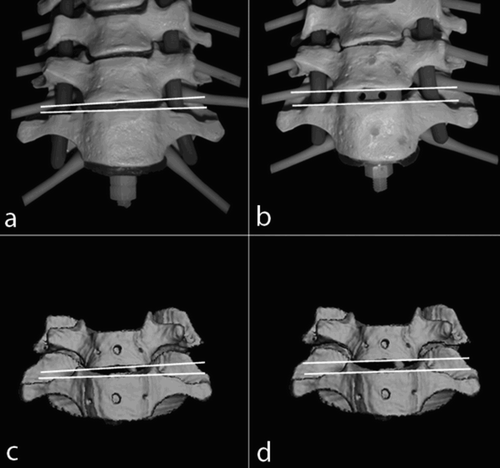
Figure 4. Computed 3D reconstruction before (c) and after (d) simulated cage-fusion C6/7 compared with a digital photograph of the pre- and post-interventional spine model (a and b).

Table I.  Sites of microsensor implantation

Figure 5. Due to the differing anatomy of the individual vertebral bodies of the cervical spine, different locations were sought for the intermittent implantation of microsensors.
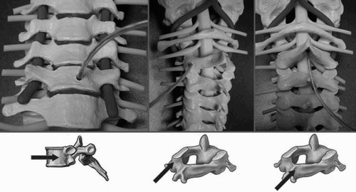
Figure 5. Due to the differing anatomy of the individual vertebral bodies of the cervical spine, different locations were sought for the intermittent implantation of microsensors.

Figure 6. System monitor screenshot showing the 3D reconstruction model and axial, transverse and sagittal tomographic planes.
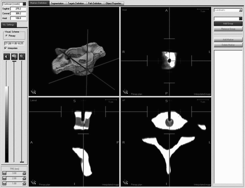
Figure 6. System monitor screenshot showing the 3D reconstruction model and axial, transverse and sagittal tomographic planes.

Figure 7. Mean position errors (PEr) for rotation around the longitudinal (a), sagittal (b) and transversal (c) axes.
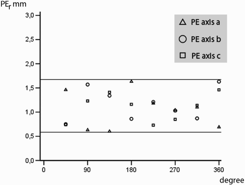
Figure 7. Mean position errors (PEr) for rotation around the longitudinal (a), sagittal (b) and transversal (c) axes.

Figure 8. Mean position errors (PEs) for displacement/shift along the longitudinal (L), sagittal (S) and transversal (T) axes.
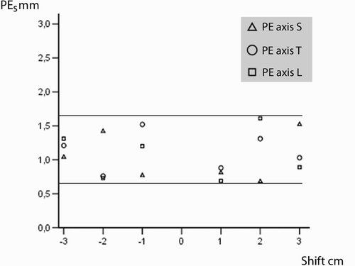
Figure 8. Mean position errors (PEs) for displacement/shift along the longitudinal (L), sagittal (S) and transversal (T) axes.

Figure 9. During the simulated surgical operations, the relative positions of the vertebral body upper plates (λ), the height of the individual space in the a.p. projection (a), the distance of the anterior edges of the body in the lateral projection (b), the distance of the spinous processes from each other in the lateral projection (c), and the angular relationship of the spinous processes in the craniocaudal projection (δ) are determined.
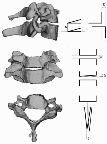
Figure 9. During the simulated surgical operations, the relative positions of the vertebral body upper plates (λ), the height of the individual space in the a.p. projection (a), the distance of the anterior edges of the body in the lateral projection (b), the distance of the spinous processes from each other in the lateral projection (c), and the angular relationship of the spinous processes in the craniocaudal projection (δ) are determined.

Table II.  Biomechanical changes after different surgical procedures.

Reprints and Corporate Permissions

Please note: Selecting permissions does not provide access to the full text of the article, please see our help page How do I view content?

To request a reprint or corporate permissions for this article, please click on the relevant link below:

Academic Permissions

Please note: Selecting permissions does not provide access to the full text of the article, please see our help page How do I view content?

Obtain permissions instantly via Rightslink by clicking on the button below:

If you are unable to obtain permissions via Rightslink, please complete and submit this Permissions form. For more information, please visit our Permissions help page.