Figures & data
Figure 1. Virtual springs model. The interaction of the tissue with the needle is modeled by distributed virtual springs. [Color version available online.]
![Figure 1. Virtual springs model. The interaction of the tissue with the needle is modeled by distributed virtual springs. [Color version available online.]](/cms/asset/b85e3fd9-7bb3-4542-a581-9e7e5e1f87de/icsu_a_189223_f0001_b.jpg)
Figure 2. Linear system model. A flexible beam subjected to a number of virtual springs. [Color version available online.]
![Figure 2. Linear system model. A flexible beam subjected to a number of virtual springs. [Color version available online.]](/cms/asset/de14f91d-6a36-455a-b923-0cc4bd89f5ab/icsu_a_189223_f0002_b.jpg)
Figure 3. Several needle path solutions for the same tip position with different tip inclinations. [Color version available online.]
![Figure 3. Several needle path solutions for the same tip position with different tip inclinations. [Color version available online.]](/cms/asset/b492ea57-ab75-487f-8fb1-ab233b0cecd7/icsu_a_189223_f0003_b.jpg)
Figure 4. Needle insertion simulation for tip orientation tangent to the path. [Color version available online.]
![Figure 4. Needle insertion simulation for tip orientation tangent to the path. [Color version available online.]](/cms/asset/f60ca8b1-14cc-491e-8645-a3ef76f0244d/icsu_a_189223_f0004_b.jpg)
Figure 5. Needle insertion simulation minimizing lateral pressure on the tissue. [Color version available online.]
![Figure 5. Needle insertion simulation minimizing lateral pressure on the tissue. [Color version available online.]](/cms/asset/85e2976a-90c5-4352-a3a5-d9ee9e399246/icsu_a_189223_f0005_b.jpg)
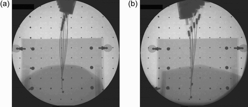
Figure 6. Needle insertion by robot corresponding to simulation steps 1, 3, 4 and 6 (see ). [Color version available online.]
![Figure 6. Needle insertion by robot corresponding to simulation steps 1, 3, 4 and 6 (see Figure 5). [Color version available online.]](/cms/asset/56a81af7-64ea-45f8-b33d-35898966e5ff/icsu_a_189223_f0006_b.jpg)
Figure 7. a) Experimental setup with X-ray imaging. b) Spinal needle, force sensor and liver tissue. [Color version available online.]
![Figure 7. a) Experimental setup with X-ray imaging. b) Spinal needle, force sensor and liver tissue. [Color version available online.]](/cms/asset/dd471c40-0f62-4650-9d6c-5c2301d92dfb/icsu_a_189223_f0007_b.jpg)
![Figure 8. a) Needle and tissue image. b) Detected needle and planned insertion path. [Color version available online.]](/cms/asset/4c85c7cc-08d9-4b29-9cbc-0f2a076817f0/icsu_a_189223_f0008_b.jpg)
