Figures & data
Table I. Surgical protocol for minimally invasive keyhole neurosurgeries.
Table II. Characteristics of support techniques for minimally invasive keyhole neurosurgery according to the steps in . Steps 1(b) and 2(a) are common to all; + and − indicate a relative advantage/disadvantage.
Table III. Characteristics of support techniques for minimally invasive keyhole neurosurgery (+ + +indicates the most advantageous, + the least). Criteria assessed are as follows (from left to right): clinical accuracy, range of applicability, ease of use in the OR, intraoperative adaptability of preoperative plan, bulk (size and weight), patient morbidity, and cost.
Figure 1. System concept: (a) The MARS robot mounted on the skull. (b) Skull-mounted pins. (c) The robot mounting base. [colour version available online.]
![Figure 1. System concept: (a) The MARS robot mounted on the skull. (b) Skull-mounted pins. (c) The robot mounting base. [colour version available online.]](/cms/asset/d7bebd34-33d5-486c-b7cd-905b60d1fae2/icsu_a_190854_f0001_b.jpg)
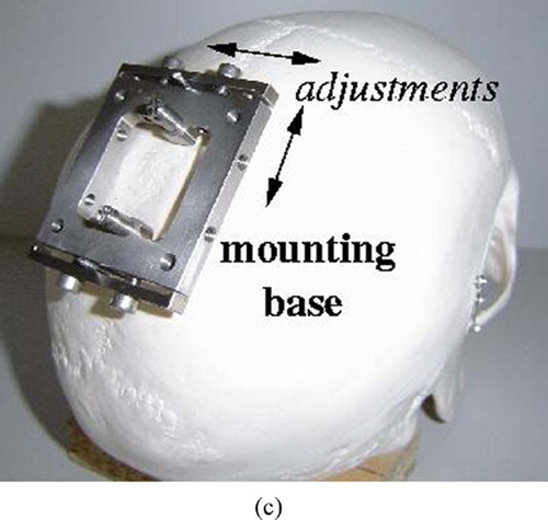
Figure 2. Preoperative planning module screens. (a) Entry and target point selection. (b) Robot base location and range. [colour version available online.]
![Figure 2. Preoperative planning module screens. (a) Entry and target point selection. (b) Robot base location and range. [colour version available online.]](/cms/asset/95e93487-2ae1-413f-b2ee-57e6392c075a/icsu_a_190854_f0002_b.jpg)
Figure 3. Preoperative robot placement computation.
Figure 4. Intraoperative robot positioning augmented reality images. (a) Starting position. (b) Middle position. (c) Final position. [colour version available online.]
![Figure 4. Intraoperative robot positioning augmented reality images. (a) Starting position. (b) Middle position. (c) Final position. [colour version available online.]](/cms/asset/141b923f-a7e3-4d97-9b5e-80a5e2d02311/icsu_a_190854_f0004_b.jpg)
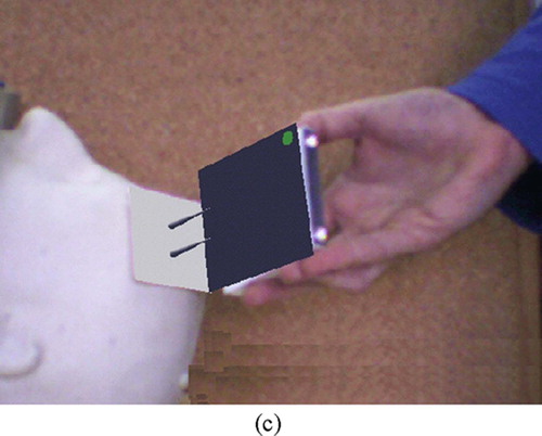
Figure 5. Intraoperative robot positioning computation.
Figure 6. Registration between intraoperative surface scan and preoperative surface model from CT/MRI. (a) Before registration. (b) After registration. [colour version available online.]
![Figure 6. Registration between intraoperative surface scan and preoperative surface model from CT/MRI. (a) Before registration. (b) After registration. [colour version available online.]](/cms/asset/3cc983d4-7629-4320-8277-5ba77c071b63/icsu_a_190854_f0006_b.jpg)
Figure 7. The registration jig. (a) Photograph. (b) A scan showing the four vertex points. [colour version available online.]
![Figure 7. The registration jig. (a) Photograph. (b) A scan showing the four vertex points. [colour version available online.]](/cms/asset/ad81392a-1868-4194-aa52-71d921fa65c6/icsu_a_190854_f0007_b.jpg)
Table IV. MRI/laser scan registration error for 19 data-set pairs of two patients. Columns indicate MRI scans and patient attitude (worried or relaxed, eyes closed or open). Rows indicate surface scans, attitude (worried or relaxed, eyes closed in all cases) and the distance between the surface scanner and the patient's face. Each entry shows the mean (standard deviation) surface registration error in millimetres. The overall RMS error is 1 mm (SD = 0.95 mm) computed in 2 seconds.
Figure 8. Two views of the phantom model created from MRI data, augmented with registration fiducials and target fiducials inside the skull. The detail shows the geometry of the fiducial. (a) Side view. (b) Top view. [colour version available online.]
![Figure 8. Two views of the phantom model created from MRI data, augmented with registration fiducials and target fiducials inside the skull. The detail shows the geometry of the fiducial. (a) Side view. (b) Top view. [colour version available online.]](/cms/asset/7560def2-c2d4-4f44-9c42-0720f257f403/icsu_a_190854_f0008_b.jpg)
Figure 9. In vitro experimental setup. (a) Front view, with registration jig. (b) Side view with robot. [colour version available online.]
![Figure 9. In vitro experimental setup. (a) Front view, with registration jig. (b) Side view with robot. [colour version available online.]](/cms/asset/4fb82c1b-60dc-490e-816d-2ef8276e284f/icsu_a_190854_f0009_b.jpg)
Figure 10. Registration chains for the in vitro experiment. Each box corresponds to an independent coordinate system. The location of the phantom targets with respect to the robot base origin is computed once via the surface scanner (phantom/scanner and robot/scanner transformations) using the face and registration face surfaces, and once via the optical tracker (phantom tracker and robot/tracker transformations) using the registration jig and the face fiducials. By construction, the phantom and the MRI are in the same coordinate system.
Table V. In vitro registration results (in mm) of five experiments. The second and third columns are the surface scanner phantom and robot base surface registration errors. The fourth and fifth columns are the fiducial tracker phantom and registration jig registration errors (both FRE – Fiducial Registration Error – and TRE – Target Registration Error – for a target approximately 150 mm from the mounting base. The last column is the error between the target scanner and tracker fiducial locations.
Table VI. In vitro registration results (in mm) of four trial experiments. The first column shows the run number. The second column shows the surface scanner registration error with respect to the phantom. The third column shows the target name inside the brain. The fourth, fifth, and sixth columns show needle errors at the entry point and target, and the trajectory angular error. The bottom row shows the average and standard deviation over all 22 trials and targets.