Figures & data
Figure 1. Endoscopic trans-nasal pituitary surgery: (a) OR set-up; (b) sagittal image of the head featuring the pituitary gland, parasellar bones, brain and cranium; (c) oblique image featuring the pituitary gland and surrounding critical tissues (reproduced with permission from reference Citation[2]). [Color version available online.]
![Figure 1. Endoscopic trans-nasal pituitary surgery: (a) OR set-up; (b) sagittal image of the head featuring the pituitary gland, parasellar bones, brain and cranium; (c) oblique image featuring the pituitary gland and surrounding critical tissues (reproduced with permission from reference Citation[2]). [Color version available online.]](/cms/asset/70260b86-a90d-4973-a254-c566f03e830f/icsu_a_216668_f0001_b.gif)
Figure 2. Tissue map computation from CT and MR, exploiting the tubular structure of critical tissues and the embedded structure of other soft tissues (from reference Citation[6]). [Color version available online.]
![Figure 2. Tissue map computation from CT and MR, exploiting the tubular structure of critical tissues and the embedded structure of other soft tissues (from reference Citation[6]). [Color version available online.]](/cms/asset/88a4797f-592f-460b-bcd5-bc6435213c66/icsu_a_216668_f0002_b.gif)
Figure 3. Tissue-guided simplex models: (a) 2-simplex mesh and dual triangulation; (b) T1 and T2 Eulerian operators defined on 2-simplex mesh. Prior results Citation[19]: (c) radially varying simplex and (d) dual triangulated surface, topologically equivalent to a sphere. This topological limitation is addressed in the current paper. [Color version available online.]
![Figure 3. Tissue-guided simplex models: (a) 2-simplex mesh and dual triangulation; (b) T1 and T2 Eulerian operators defined on 2-simplex mesh. Prior results Citation[19]: (c) radially varying simplex and (d) dual triangulated surface, topologically equivalent to a sphere. This topological limitation is addressed in the current paper. [Color version available online.]](/cms/asset/d83b8998-caa0-470a-a956-dc4c5ac7273e/icsu_a_216668_f0003_b.gif)
Figure 5. Contrasting decimation methods on a synthetic invaginated cube surface, featuring a hemispheric inner gland: (a) wireframe of MC results; (b) existing decimation method Citation[13] displayed as a 3D wireframe overlaid on a surface rendering; (c) and (d) radially varying simplex mesh, featuring final simplex and dual triangular results. [Color version available online.]
![Figure 5. Contrasting decimation methods on a synthetic invaginated cube surface, featuring a hemispheric inner gland: (a) wireframe of MC results; (b) existing decimation method Citation[13] displayed as a 3D wireframe overlaid on a surface rendering; (c) and (d) radially varying simplex mesh, featuring final simplex and dual triangular results. [Color version available online.]](/cms/asset/849d4187-0688-4e89-850f-f120c14ebebd/icsu_a_216668_f0005_b.gif)
Figure 6. Contrasting decimation methods on the brain surface: (a) the existing method, featuring a wireframe of the overall brain surface mesh and a closeup of the wireframe overlaid on the rendering of the brain surface, centered on the pituitary gland; (b) a radially varying simplex mesh, featuring wireframe and overlay closeup views as in (a); (c) a radially varying triangular surface, dual to the simplex mesh in (b). (d) Decimation statistics: (top) the number of faces, and (bottom) the average distance to the boundary plotted against simplex iteration, in going from the dual of (a) to (b) (2618 to 1051 faces). [Color version available online.]
![Figure 6. Contrasting decimation methods on the brain surface: (a) the existing method, featuring a wireframe of the overall brain surface mesh and a closeup of the wireframe overlaid on the rendering of the brain surface, centered on the pituitary gland; (b) a radially varying simplex mesh, featuring wireframe and overlay closeup views as in (a); (c) a radially varying triangular surface, dual to the simplex mesh in (b). (d) Decimation statistics: (top) the number of faces, and (bottom) the average distance to the boundary plotted against simplex iteration, in going from the dual of (a) to (b) (2618 to 1051 faces). [Color version available online.]](/cms/asset/77d1c027-1ca4-4ae3-9af7-8f253cafbd1e/icsu_a_216668_f0006_b.gif)
Figure 7. Clinically useful meshing: superposition of relevant critical tissue meshes with the brain surface. Basilar arteries and optic and oculomotor nerves are shown as triangular mesh. [Color version available online.]
![Figure 7. Clinically useful meshing: superposition of relevant critical tissue meshes with the brain surface. Basilar arteries and optic and oculomotor nerves are shown as triangular mesh. [Color version available online.]](/cms/asset/0122f0dc-3e34-4e8b-817c-661ae8157e53/icsu_a_216668_f0007_b.gif)
Figure 8. The use of radial and path-based distance to convert “distant” extra-cranial soft tissue to tissue of null displacement and determine edge scale: (a) original tissue map Citation[6]; (b) null-displacement tissue (in orange); (c) final wireframe and rendering of triangulated surface, with dense results visible within 10 mm of the path. [Color version available online.]
![Figure 8. The use of radial and path-based distance to convert “distant” extra-cranial soft tissue to tissue of null displacement and determine edge scale: (a) original tissue map Citation[6]; (b) null-displacement tissue (in orange); (c) final wireframe and rendering of triangulated surface, with dense results visible within 10 mm of the path. [Color version available online.]](/cms/asset/4ade7967-e052-45ad-98b8-802b03f33043/icsu_a_216668_f0008_b.gif)
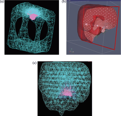
Figure 9. Topologically accurate, radially varying brain volume tetrahedralization: (a) invaginated cube visualized as 3D wireframe of all tetrahedral edges, with child mesh in pink and parent mesh in turquoise; (b) brain mesh visualized as semi-transparent boundary of clipped volume, where triangular intersections of tetrahedra with the clipping plane are shown as a white wireframe; and (c) brain mesh visualized as a 3D wireframe rendering.

Figure 10. Distributions of (a) dihedral angles of edge pairs, (b) edge length over length-objective, and (c) number of shared tetrahedra for each vertex.

