Figures & data
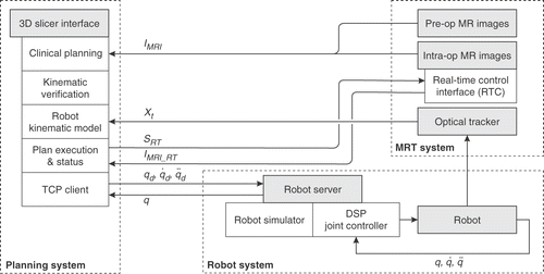
Figure 1. The percutaneous intervention system, comprising a planning sub-system, the MRT, and an MR-compatible robot.

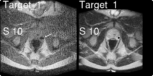
Figure 2. Images displayed to the physician during the procedure: FSE real-time image (left) showing needle artifact (arrow), and T2-weighted pre-procedure image (right) with a target marked in the peripheral zone. Distance to the target (superior 10 mm) is also displayed.

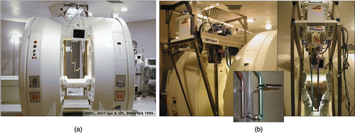
Figure 3. (a) GE Signa SP open-MRI scanner, with (b) integrated 5-DOF MR-compatible robot. The robot end-effector is equipped with an optical tracking marker (inset).

Figure 5. Phantom experiments: (a) scale models of legs and PVC prostate phantom with embedded targets; (b) patient model and robot placement inside the scanner with sterile draping; (c) needle trajectories are interactively specified in the planning environment. [Color version available online.]
![Figure 5. Phantom experiments: (a) scale models of legs and PVC prostate phantom with embedded targets; (b) patient model and robot placement inside the scanner with sterile draping; (c) needle trajectories are interactively specified in the planning environment. [Color version available online.]](/cms/asset/30ca5ced-5635-406d-ba4a-22924323de50/icsu_a_216751_f0005_b.gif)
Figure 6. (a) Real-time image visualization in the Slicer interface during needle insertion; (b, c) MRI images of needle placement in the phantom; and (d) the target phantom. [Color version available online.]
![Figure 6. (a) Real-time image visualization in the Slicer interface during needle insertion; (b, c) MRI images of needle placement in the phantom; and (d) the target phantom. [Color version available online.]](/cms/asset/4af003fc-c7c8-44c3-8854-4b47236d1ecf/icsu_a_216751_f0006_b.gif)
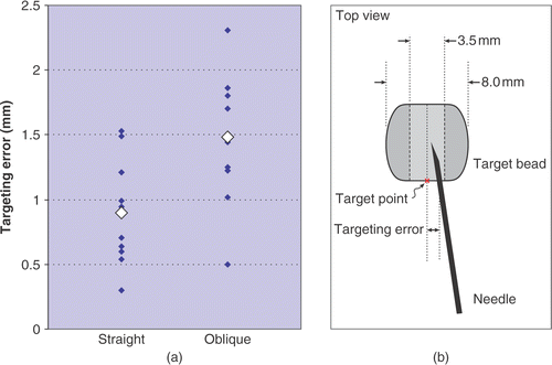
Figure 7. Needle placement accuracy measured during phantom experiments: (a) placement error for 10 straight needle trajectories and 11 oblique trajectories; (b) a schematic showing the top view and dimensions of the target beads and error measurement.

Table 1. Measured needle placement accuracy.

![Figure 8. Closed-bore concept for MRI-guided needle placement. The patient's legs are placed on a leg support that provides a “tunnel” of access to the perineum. A compact robotic needle driver mechanism is placed into this tunnel as shown. [Color version available online.]](/cms/asset/375acc72-e6ce-4261-8f33-b53f16319ad8/icsu_a_216751_f0008_b.gif)