Figures & data
Figure 1. Standard fluoroscopic-based navigation for cannulated screw insertion. The dynamic reference frame (labeled RF) is attached to the iliac crest. A tracked drill guide (DG) is used for planning the screw's trajectory, and a guide wire is than inserted through it. The computer display (CD) displays the virtual image of the drill guide trajectory (green line) on both the AP and lateral views simultaneously. [Color version available online.]
![Figure 1. Standard fluoroscopic-based navigation for cannulated screw insertion. The dynamic reference frame (labeled RF) is attached to the iliac crest. A tracked drill guide (DG) is used for planning the screw's trajectory, and a guide wire is than inserted through it. The computer display (CD) displays the virtual image of the drill guide trajectory (green line) on both the AP and lateral views simultaneously. [Color version available online.]](/cms/asset/92f6220a-f7e1-4c54-a503-1124f28749dc/icsu_a_229935_f0001_b.gif)
Figure 2. The validation phase. New images are taken after the insertion of the guide wires. The drill guide is placed over the wires and the navigated virtual image (green line) is superimposed on the “real” radiographic image (black line). The discrepancy between these images in both translation and angulation is calculated. [Color version available online.]
![Figure 2. The validation phase. New images are taken after the insertion of the guide wires. The drill guide is placed over the wires and the navigated virtual image (green line) is superimposed on the “real” radiographic image (black line). The discrepancy between these images in both translation and angulation is calculated. [Color version available online.]](/cms/asset/978f931c-2258-42f2-978a-9dbed6ee8412/icsu_a_229935_f0002_b.gif)
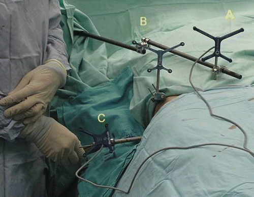
Figure 3. Table-mounted (A) and iliac-crest–mounted (B) dynamic reference frame attachments. The drill guide (C) is also visible.

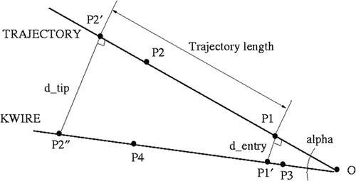
Figure 4. Determination of the trajectory translation at the entry point (d_entry) and tip (d_tip), and of the angle between the trajectory image and the k-wire fluoroscopic images (alpha).

Table I. Translational offset (in mm) of the trajectory from the drill guide at the two sites (d_tip and d_entry) in the AP view.
Table II. Translational offset (in mm) of the trajectory from the drill guide at the two sites (d_tip and d_entry) in the lateral view.
Table III. Angular offset (in degrees) in the AP and lateral views.