Figures & data
Figure 1. (a) The FastSCAN™ wand with transmitter. (b) The wand is swept over an object when performing a scan in a manner analogous to spray painting. (c) While scanning, a real-time point cloud or (in this case) surface representation is shown on a computer display to enable the user to see what has been scanned. Here, only the articular surface has been scanned, as this is what will be registered to the CT dataset.

Figure 2. A visualization of the four digitized landmarks fitted to simple geometries. [Color version available online.]
![Figure 2. A visualization of the four digitized landmarks fitted to simple geometries. [Color version available online.]](/cms/asset/30aafc0f-ac14-48b1-b1f1-bb85498490b2/icsu_a_251611_f0002_b.gif)
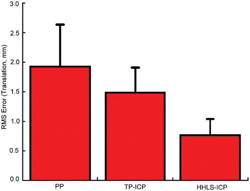
Figure 3. Mean RMS registration error (+1 SD) for the three registration techniques evaluated (in mm). The implementation of the surface-based registration produced not only improved registration accuracy, but also a more consistent result, as evidenced by the smaller standard deviation shown on the bars at far right. The HHLS-ICP method was the most accurate and consistent of the three techniques.

Table I. RMS target registration error: translation (SD in parentheses).
Figure 4. Internal-external (top) and varus-valgus (bottom) mean (dashed line) and maximum (dotted line) error in the flexion-extension axis determination for three methods (PP – left; TP-ICP – center; and HHLS-ICP – right). The solid line represents the target flexion-extension axis. All units are in mm. [Color version available online.]
![Figure 4. Internal-external (top) and varus-valgus (bottom) mean (dashed line) and maximum (dotted line) error in the flexion-extension axis determination for three methods (PP – left; TP-ICP – center; and HHLS-ICP – right). The solid line represents the target flexion-extension axis. All units are in mm. [Color version available online.]](/cms/asset/806db2d1-7a72-4c32-aafc-9754a35e06c9/icsu_a_251611_f0004_b.gif)
Table II. Directional shift in the flexion-extension axis. A shift in the positive x-direction represents a shift in the anterior direction; a shift in the positive y-direction represents a shift in the superior direction; and a shift in the positive z-direction represents a shift in the medial direction.