Figures & data
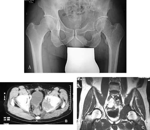
Figure 1. Plain radiograph (A), CT scan (B) and MRI scan (C) of patient's pelvis, showing a destructive bony metastasis involving the left acetabular region.

Figure 2. Computer-aided design custom pelvic prosthesis for skeletal reconstruction after periacetabular tumor resection. [Color version available online.]
![Figure 2. Computer-aided design custom pelvic prosthesis for skeletal reconstruction after periacetabular tumor resection. [Color version available online.]](/cms/asset/58fa0e0f-ac72-416a-bb2e-1a4eb2fa1aa6/icsu_a_253465_f0002_b.gif)
Figure 3. The most important and easily identifiable bony landmark was point 1, which was the intersection point between the acetabular rim and the anterior inferior iliac spine. Other points and measurements were all based on point 1. Point 3 and other points at the acetabular rim were arbitrary. The custom pelvic prosthesis was designed in such a way that orientation of the superior surface of the prosthesis is parallel to the ground when the patient is in a standing position. When a person stands upright, the plane formed by the two anterior superior iliac spines and pubic tubercles is perpendicular to the ground. Therefore, orientation of the prosthesis and bony resection could be defined and planned using this plane. Based on points 2 and 4 and the above information, the plane and level of bony resection could be defined with points 1–4 in the navigation planning. Other points and distances were used to verify the accuracy of this plane definition. [Color version available online.]
![Figure 3. The most important and easily identifiable bony landmark was point 1, which was the intersection point between the acetabular rim and the anterior inferior iliac spine. Other points and measurements were all based on point 1. Point 3 and other points at the acetabular rim were arbitrary. The custom pelvic prosthesis was designed in such a way that orientation of the superior surface of the prosthesis is parallel to the ground when the patient is in a standing position. When a person stands upright, the plane formed by the two anterior superior iliac spines and pubic tubercles is perpendicular to the ground. Therefore, orientation of the prosthesis and bony resection could be defined and planned using this plane. Based on points 2 and 4 and the above information, the plane and level of bony resection could be defined with points 1–4 in the navigation planning. Other points and distances were used to verify the accuracy of this plane definition. [Color version available online.]](/cms/asset/64f9b109-4d24-4c8a-8fbe-9d39b84fb6be/icsu_a_253465_f0003_b.gif)
Figure 4. The cut surface of the ilium after pelvic resection under navigational guidance (A); after preoperative simulation of the pelvic resection in the plaster model (B); and at the predetermined level of pelvic resection on CAD data (C). [Color version available online.]
![Figure 4. The cut surface of the ilium after pelvic resection under navigational guidance (A); after preoperative simulation of the pelvic resection in the plaster model (B); and at the predetermined level of pelvic resection on CAD data (C). [Color version available online.]](/cms/asset/273b751e-52fa-488e-b5ba-088974a7ade6/icsu_a_253465_f0004_b.gif)
Figure 5. Intraoperative screen images on the navigation monitor. The location of the navigated diathermy electrode (white line) was seen in relation to the peri-acetabular tumor. The proximal margin and location of planned screws could be identified in coronal images (A), obliques images (B), and reconstructed three-dimensional images (C). In panel D, a dynamic reference base tracker is seen attached to the left iliac crest, with a navigated diathermy electrode being used to identify the virtual margin and the resection level on the navigation monitor. [Color version available online.]
![Figure 5. Intraoperative screen images on the navigation monitor. The location of the navigated diathermy electrode (white line) was seen in relation to the peri-acetabular tumor. The proximal margin and location of planned screws could be identified in coronal images (A), obliques images (B), and reconstructed three-dimensional images (C). In panel D, a dynamic reference base tracker is seen attached to the left iliac crest, with a navigated diathermy electrode being used to identify the virtual margin and the resection level on the navigation monitor. [Color version available online.]](/cms/asset/c161e679-a16e-4abb-b921-021267464ddf/icsu_a_253465_f0005_b.gif)
