832
Views
12
CrossRef citations to date
0
Altmetric
Biomedical Paper

CT-based planning of a single-radius femoral component in total knee arthroplasty using the ROBODOC system

, , , &
Pages 23-29 | Received 08 Nov 2006, Accepted 16 Nov 2007, Published online: 06 Jan 2010

Figures & data

Figure 1. Three-dimensional preoperative planning on ORTHODOC.

Figure 1. Three-dimensional preoperative planning on ORTHODOC.

Figure 2. The transepicondylar axis was determined by connecting the most prominent points of both the medial and lateral epicondyles in both the coronal plane (a) and the axial plane (b).
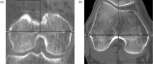
Figure 2. The transepicondylar axis was determined by connecting the most prominent points of both the medial and lateral epicondyles in both the coronal plane (a) and the axial plane (b).

Figure 3. Virtual implantation of the femoral component. The implant size was selected according to the radius (shown as a circle) that was closest to the distance between the TEA (the center of the two orthogonal axes in this view) and the distal condyle border in the lateral condyle.
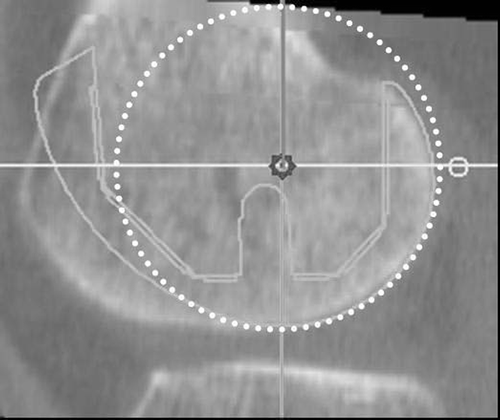
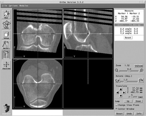
Figure 3. Virtual implantation of the femoral component. The implant size was selected according to the radius (shown as a circle) that was closest to the distance between the TEA (the center of the two orthogonal axes in this view) and the distal condyle border in the lateral condyle.
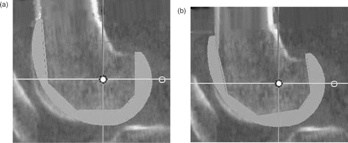
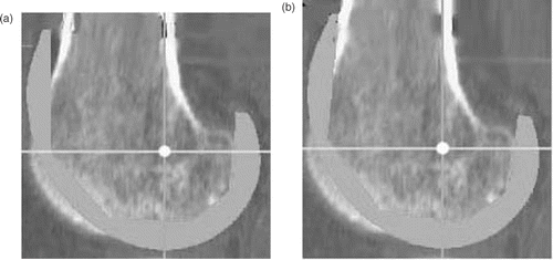
Figure 4. Flexion of component. When the antero-superior apex of the femoral component dug into the anterior cortex of the femur (a), the femoral component was flexed around the TEA to avoid creation of a notch (b).

Figure 4. Flexion of component. When the antero-superior apex of the femoral component dug into the anterior cortex of the femur (a), the femoral component was flexed around the TEA to avoid creation of a notch (b).

Figure 5. Extension of component. When a gap occurred between the apex and the anterior cortex (a), the implant was rotated into extension until contact was obtained between the anterior cortex and the matching surface of the prosthesis (b).

Figure 5. Extension of component. When a gap occurred between the apex and the anterior cortex (a), the implant was rotated into extension until contact was obtained between the anterior cortex and the matching surface of the prosthesis (b).

Reprints and Corporate Permissions

Please note: Selecting permissions does not provide access to the full text of the article, please see our help page How do I view content?

To request a reprint or corporate permissions for this article, please click on the relevant link below:

Academic Permissions

Please note: Selecting permissions does not provide access to the full text of the article, please see our help page How do I view content?

Obtain permissions instantly via Rightslink by clicking on the button below:

If you are unable to obtain permissions via Rightslink, please complete and submit this Permissions form. For more information, please visit our Permissions help page.