Figures & data
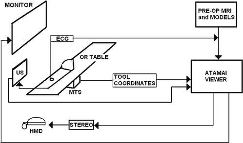
Figure 1. Schematic displaying the layout of our VR-enhanced US guidance surgical system, its components, and its typical configuration within an OR. Integrated ultrasound and virtual reality data can be delivered to the surgeon either via a monitor over the operating table, or via head-mounted display (HMD) units.

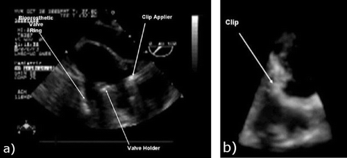
Figure 2. a) Two-dimensional TEE image of the valve tool and clip applier inside a beating porcine heart. b) Three-dimensional US image of a similar scene. Note the difficulty in interpreting the anatomical features and surgical tools and the limited field of view with 3D US.

Figure 3. a) Image of the prior high-resolution average heart model at mid-diastole (MD). b) Prior model at mid-diastole showing two segmented features of interest: the left ventricle surface and the mitral valve annulus. [Color version available online.]
![Figure 3. a) Image of the prior high-resolution average heart model at mid-diastole (MD). b) Prior model at mid-diastole showing two segmented features of interest: the left ventricle surface and the mitral valve annulus. [Color version available online.]](/cms/asset/15babe8c-e269-481c-8087-348db6dc5620/icsu_a_295282_f0003_b.gif)
Table I. Root-mean-square (RMS) distance between the model-predicted MVA and the gold-standard (US-extracted) MVA, quantified at four phases throughout the cardiac cycle.
Figure 4. a) AtamaiViewer screen-shot showing real-time intra-operative TEE data augmented with anatomical context provided by the pre-operative heart model using the feature-based registration. [Color version available online.]
![Figure 4. a) AtamaiViewer screen-shot showing real-time intra-operative TEE data augmented with anatomical context provided by the pre-operative heart model using the feature-based registration. [Color version available online.]](/cms/asset/85031747-93bb-41c6-b6d7-66c649e81b26/icsu_a_295282_f0004_b.gif)
Figure 5. a) Physical representation of a mechanical mitral valve attached to the valve-insertion tool. b) Virtual representation of the valve and valve-insertion tool. c) Virtual surgical environment employed during a preliminary in vivo porcine study, including the pre-operative heart model, intra-operative TEE image, tracked TEE probe, and surgical tools. [Color version available online.]
![Figure 5. a) Physical representation of a mechanical mitral valve attached to the valve-insertion tool. b) Virtual representation of the valve and valve-insertion tool. c) Virtual surgical environment employed during a preliminary in vivo porcine study, including the pre-operative heart model, intra-operative TEE image, tracked TEE probe, and surgical tools. [Color version available online.]](/cms/asset/ceac8520-5c38-4a78-b0a6-1b700bac58e4/icsu_a_295282_f0005_b.gif)
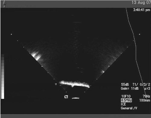
Figure 6. Ultrasound images of a point-source Teflon sphere (approximately 1.6 mm in diameter). The point source is located on top of a layer of Sorbothane and is imaged upside-down using each of the three US transducers (TTE, adult TEE, and pediatric TEE).

Table II. Point-source localization accuracy using three different US probes and two different calibration methods. The root-mean-square (RMS) of the distance errors is provided.
Table III. Single point localization accuracy assessment. Three users were asked to localize a point three times for each of the three modalities; N = 9 for each modality. An ANOVA showed that only the modality had a significant difference.
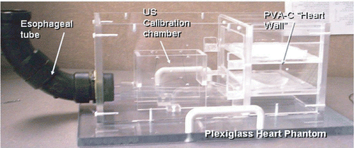
Figure 7. Plexiglass cardiac intervention phantom showing the “esophagus” - the black tube where the TEE probe is inserted to simulate the intra-operative application - and PVA-C membranes representing heart wall tissue.

Figure 8. a) A valve poorly implanted under US guidance in the cardiac phantom. Arrows indicate the location of the fasteners. b) Endoscopic view showing valve placement under US guidance in an excised heart. c) Endoscopic view showing a fastener incorrectly inserted under US guidance in an excised heart.

Figure 9. a) Correct valve implantation under VR-enhanced US guidance in the cardiac phantom. b) Endoscopic image showing the appropriate positioning (also confirmed by the clear view of the chordae tendinae) of the valve onto the native mitral annulus of an excised heart using US guidance augmented by the VR environment. c) Post-procedure image showing the correct location of the fasteners around the valve achieved under US-VR guidance in an excised heart. [Color version available online.]
![Figure 9. a) Correct valve implantation under VR-enhanced US guidance in the cardiac phantom. b) Endoscopic image showing the appropriate positioning (also confirmed by the clear view of the chordae tendinae) of the valve onto the native mitral annulus of an excised heart using US guidance augmented by the VR environment. c) Post-procedure image showing the correct location of the fasteners around the valve achieved under US-VR guidance in an excised heart. [Color version available online.]](/cms/asset/d5e766cf-7bb3-492f-a888-899bddbf90dc/icsu_a_295282_f0009_b.gif)