844
Views
6
CrossRef citations to date
0
Altmetric
Biomedical Paper

An integer programming model for distal humerus fracture fixation planning

, , , & , Ph.D.
Pages 139-147 | Received 16 Apr 2007, Accepted 10 Mar 2008, Published online: 06 Jan 2010

Figures & data

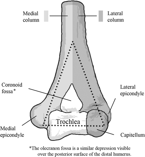
Figure 1. Anatomy of the distal humerus. The anterior view is shown.

Figure 1. Anatomy of the distal humerus. The anterior view is shown.

Figure 2. OTA classification of complete articular fractures of the distal humerus (13C): (1) articular simple, metaphyseal simple; (2) articular simple, metaphyseal multifragmentary; and (3) multifragmentary.
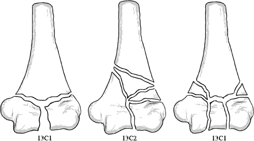
Figure 2. OTA classification of complete articular fractures of the distal humerus (13C): (1) articular simple, metaphyseal simple; (2) articular simple, metaphyseal multifragmentary; and (3) multifragmentary.

Figure 3. The graphical user interface (GUI) of the system developed for surgical planning. The controls on the right allow the user to load a fracture configuration and generate a solution. Controls are also provided to view the weighting scheme used to generate the solutions.
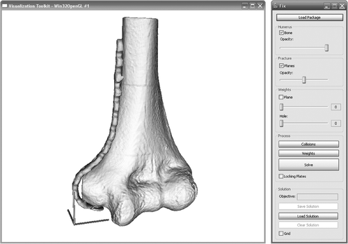
Figure 3. The graphical user interface (GUI) of the system developed for surgical planning. The controls on the right allow the user to load a fracture configuration and generate a solution. Controls are also provided to view the weighting scheme used to generate the solutions.

Figure 4. One plane of the 3D grid used by the weighting scheme for a 13C3 fracture: (a) grid with bone model in place; (b) grid with bone model removed.
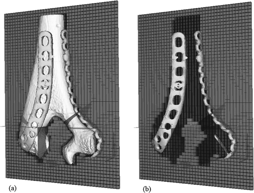
Figure 4. One plane of the 3D grid used by the weighting scheme for a 13C3 fracture: (a) grid with bone model in place; (b) grid with bone model removed.

Figure 5. Possible screw orientations in each configuration: (a) 1 deviation, 4 planes; (b) 1 deviation, 8 planes; (c) 4 deviations, 4 planes; (d) 4 deviations, 8 planes.
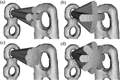
Figure 5. Possible screw orientations in each configuration: (a) 1 deviation, 4 planes; (b) 1 deviation, 8 planes; (c) 4 deviations, 4 planes; (d) 4 deviations, 8 planes.

Figure 6. Solutions generated with varying degrees of freedom in screw orientation: (a) 13C1, 4 orientations, 1 deviation; (b) 13C1, 4 orientations, 4 deviations; (c) 13C1, 8 orientations, 1 deviation; (d) 13C1, 8 orientations, 4 deviations; (e) 13C2, 8 orientations, 4 deviations; (f)13C3, 8 orientations, 4 deviations.
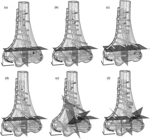
Figure 6. Solutions generated with varying degrees of freedom in screw orientation: (a) 13C1, 4 orientations, 1 deviation; (b) 13C1, 4 orientations, 4 deviations; (c) 13C1, 8 orientations, 1 deviation; (d) 13C1, 8 orientations, 4 deviations; (e) 13C2, 8 orientations, 4 deviations; (f)13C3, 8 orientations, 4 deviations.

Table I.  Pre-operative plan for 13C3 fracture generated with 4 deviations and 8 planes.

Table II.  Pre-processor problem size and processing time in seconds.

Table III.  Solver processing time in seconds.
Reprints and Corporate Permissions

Please note: Selecting permissions does not provide access to the full text of the article, please see our help page How do I view content?

To request a reprint or corporate permissions for this article, please click on the relevant link below:

Academic Permissions

Please note: Selecting permissions does not provide access to the full text of the article, please see our help page How do I view content?

Obtain permissions instantly via Rightslink by clicking on the button below:

If you are unable to obtain permissions via Rightslink, please complete and submit this Permissions form. For more information, please visit our Permissions help page.