Figures & data
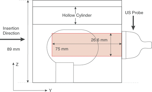
Figure 4. The tissue phantom, showing the inclusion and the hollow cylinder. [Color version available online.]
![Figure 4. The tissue phantom, showing the inclusion and the hollow cylinder. [Color version available online.]](/cms/asset/1fc0fd47-8403-429a-a7c1-3882419e114c/icsu_a_338484_f0004_b.gif)
Figure 5. Cross section of the tissue phantom, showing the position of the probe and the US imaging plane.

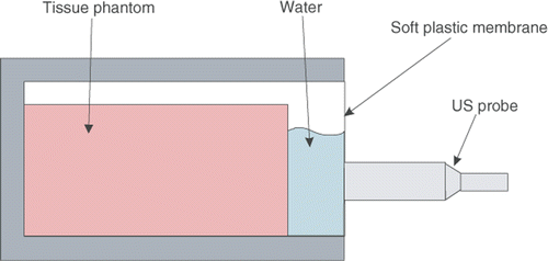
Figure 7. The schematic of the setup used for TDPE validation. The tissue phantom is in a box filled with water. The probe motion is not transmitted to the tissue phantom due to the presence of water between them.

Figure 8. The probe motion and estimated tissue displacement for different frequencies and amplitudes. In each case, the blue broken line represents the probe position and the solid red line represents the average tissue displacement in the region of interest. [Color version available online.]
![Figure 8. The probe motion and estimated tissue displacement for different frequencies and amplitudes. In each case, the blue broken line represents the probe position and the solid red line represents the average tissue displacement in the region of interest. [Color version available online.]](/cms/asset/9d280c84-885b-4a89-b689-1c47842fb6d2/icsu_a_338484_f0008_b.gif)
Table I. Validation results for TDPE.
Figure 9. (a) Needle tip position; (b) Measured insertion force; (c) Axial displacement of the mesh nodes located in the US imaging plane; and (d) Average lateral displacements of the nodes above and below the needle. The needle was partially retracted and inserted again after the main insertion. Since in the second and third insertions the needle was inserted along the same path as in the first insertion, less tissue cutting occurred. Therefore, the second and third peak forces (t = 60 and 80 s) are smaller than the first one (t = 40 s). [Color version available online.]
![Figure 9. (a) Needle tip position; (b) Measured insertion force; (c) Axial displacement of the mesh nodes located in the US imaging plane; and (d) Average lateral displacements of the nodes above and below the needle. The needle was partially retracted and inserted again after the main insertion. Since in the second and third insertions the needle was inserted along the same path as in the first insertion, less tissue cutting occurred. Therefore, the second and third peak forces (t = 60 and 80 s) are smaller than the first one (t = 40 s). [Color version available online.]](/cms/asset/a3e53afc-1261-4a6b-bf12-5cbe4eb18174/icsu_a_338484_f0009_b.gif)
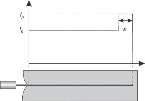
Figure 12. The measured force (red broken line) and the piece-wise linear model (solid blue line). [Color version available online.]
![Figure 12. The measured force (red broken line) and the piece-wise linear model (solid blue line). [Color version available online.]](/cms/asset/09759ae2-66cc-48b3-b7aa-7de9e5abd745/icsu_a_338484_f0012_b.gif)
Figure 13. The length L over which the force is integrated in the deformed configuration. The broken lines show the elements in the undeformed configuration. [Color version available online.]
![Figure 13. The length L over which the force is integrated in the deformed configuration. The broken lines show the elements in the undeformed configuration. [Color version available online.]](/cms/asset/3cd6e7ed-b23a-4f94-9489-5930dc5fc30a/icsu_a_338484_f0013_b.gif)
Table II. Needle shaft force density and elastic parameters.
Figure 14. Simulated and measured needle forces for two different Poisson's ratios. [Color version available online.]
![Figure 14. Simulated and measured needle forces for two different Poisson's ratios. [Color version available online.]](/cms/asset/2a4ebb5e-1400-42be-944c-393197fbd996/icsu_a_338484_f0014_b.gif)
Table III. Simulation errors.
Figure 15. Position of the nodes in the US field of view. Squares denote the original positions, stars simulated positions, and circles the positions measured with TDPE. The broken line shows the projection of the needle on the US plane. Only axial displacements are considered. The Poisson's ratio is 0.49. [Color version available online.]
![Figure 15. Position of the nodes in the US field of view. Squares denote the original positions, stars simulated positions, and circles the positions measured with TDPE. The broken line shows the projection of the needle on the US plane. Only axial displacements are considered. The Poisson's ratio is 0.49. [Color version available online.]](/cms/asset/fee69542-8096-4f24-b5e7-1b3a21164794/icsu_a_338484_f0015_b.gif)
![Figure 1. Needle insertion during prostate brachytherapy. [Color version available online.]](/cms/asset/af45b562-5804-48b6-b905-c6853244f92b/icsu_a_338484_f0001_b.gif)
![Figure 2. The experimental setup. [Color version available online.]](/cms/asset/abc3ab04-1202-448d-a910-39b7e37c9ca4/icsu_a_338484_f0002_b.gif)


![Figure 11. Tissue mesh with tetrahedral elements. [Color version available online.]](/cms/asset/09546cc4-7966-4dcd-954e-c36d4bc31c7c/icsu_a_338484_f0011_b.gif)