Figures & data
Figure 1. Overview of the computer architecture incorporated in the standard Siemens environment. The host computer is responsible for the real-time sequence compilation and initialization before it is sent for execution on the scanner. This computer also serves as the visualization computer after the image reconstruction step is over. The MRI scanner is the actual hardware that runs the pulse sequence for data acquisition. Finally, the reconstruction computer is responsible for the image generation after the data acquisition step on the scanner is completed. In the presented dedicated software environment, a feedback loop exists between the reconstruction computer and the MRI scanner which allows the pulse sequence to be modified on the fly.
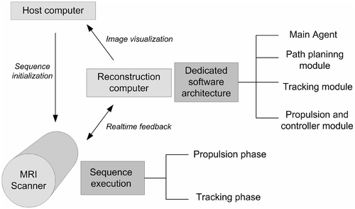
Figure 2. Overview of the real-time sequence and image calculation processes for the navigation of the magnetic sphere. A sequence kernel composed of a real-time trigger event, a propulsion phase event, and a tracking event is repeated over time. The real-time trigger event starts the control module process for the command generation, and the tracking phase calls up the position module process for the device position calculation.
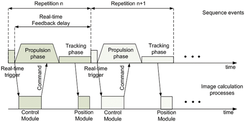
Figure 3. (a) A 3D simulation of the excited volume and corresponding projection images with the MS-SET method. When this tracking method is used during the experiment, applied RF excitation signals are tuned to the equipotential magnetic curves generated by the magnetic signature of the sphere being tracked. The 3D position of the ferromagnetic object is obtained using a correlation function performed on each k-space line of each of the three axes corresponding to the three projections necessary to determine the best possible accurate localization of the sphere within the time constraint required to guarantee stability of the feedback controller. (b) MRI images of the ferromagnetic sphere with the MS-SET method in the transversal plane. (c) Projections of the images in (b) along the readout direction.
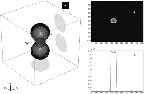
Figure 4. A 3D volume of the carotid artery of the swine filtered at 50% of the image scalar intensity range. Dots show the waypoints followed by the sphere; circles show the precision regions of radius φ. [Color version available online.]
![Figure 4. A 3D volume of the carotid artery of the swine filtered at 50% of the image scalar intensity range. Dots show the waypoints followed by the sphere; circles show the precision regions of radius φ. [Color version available online.]](/cms/asset/471d1e8e-ee80-4559-9bda-3231daf67b65/icsu_a_355295_f0004_b.gif)
Figure 5. User interface showing (1 and 2) the high-resolution MR images used to position the pig; (3) the off-resonance image used for the magnetic compatibility check and the tracking sequence calibration; (4 and 5) the Siemens sequence and protocol editor; and (6) our custom software showing the real-time position of the bead superimposed on a scale frame. [Color version available online.]
![Figure 5. User interface showing (1 and 2) the high-resolution MR images used to position the pig; (3) the off-resonance image used for the magnetic compatibility check and the tracking sequence calibration; (4 and 5) the Siemens sequence and protocol editor; and (6) our custom software showing the real-time position of the bead superimposed on a scale frame. [Color version available online.]](/cms/asset/8918eca2-e75c-4f08-8745-6842155674d6/icsu_a_355295_f0005_b.gif)