Figures & data
Figure 1. (a) Parameters related to the Heaviside function corresponding to a crack (2D case). (b) Parameters related to the crack-tip functions (2D case). (c) 2D XFEM enrichment for a single pair of one crack and one crack tip. Each node enriched with Heaviside DOFs is represented by an open circle (set J), while each node enriched with crack-tip DOFs is represented by a filled square (set K).

Figure 2. First illustration of 2D XFEM calculation: the case of a rectangular object with a crack ending inside the object. (a) Original mesh and position of the crack. (b) Final mesh resulting from application of displacements corresponding to Mode I of fracture to nodes located along the boundary of the mesh.
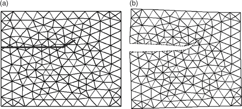
Figure 3. Second illustration of 2D XFEM calculation: the case of a rectangular object with a crack fully crossing the object. (a) Original mesh and position of the crack. (b) Final mesh resulting from the application of distinct translations to each part (more specifically, to two nodes of each part) of the mesh.
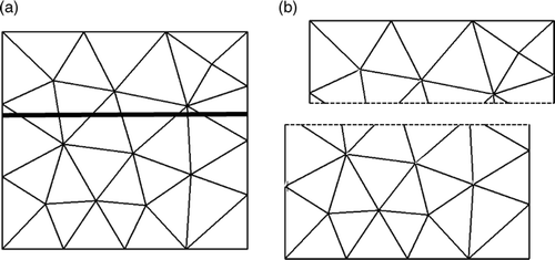
Figure 4. Block diagram of our preoperative image-update system based on biomechanical modeling of the brain.
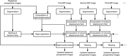
Figure 5. Two-dimensional iMR images for Case 1 (brain shift) and segmentation of the first iMR image. (1) The first iMR image, acquired before the opening of the skull and dura, and also used as a substitute preoperative image to be updated. (2) The second iMR image, acquired after the opening of the skull and dura, but prior to further surgical actions. The deformation observed is thus due to brain shift alone. (3) Segmentation of (1) into two regions: the healthy brain and the tumor.
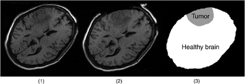
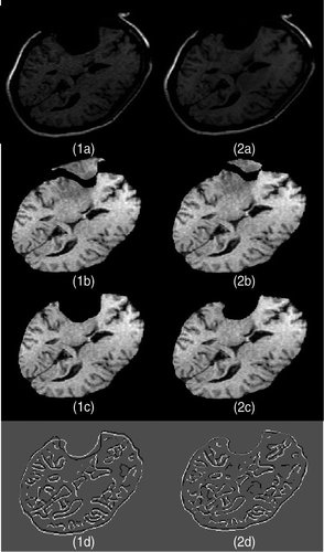
Figure 6. Two-dimensional experimental results for Case 1 (brain shift). (1a) The first iMR image. (2a) The second iMR image. (1b) Brain extracted from (1a). (2b) Deformation of (1b) using the surface displacement field of the biomechanical model, computed via FEM. (We say “surface” as we are working in two dimensions.) (1c) Juxtaposition of Canny edges of (1b) and the brain part of (2a). (2c) Juxtaposition of Canny edges of (2b) and the brain part of (2a).
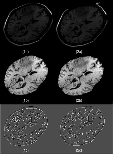
Figure 7. Two-dimensional iMR images for Case 2 (brain shift and retraction). (1) The first iMR image, acquired before the opening of the skull and dura, and also used as a substitute preoperative image to be updated. (2) The second iMR image, acquired after the opening of the skull and dura, the retraction, and the beginning of resection. The deformation observed is principally due to brain shift and retraction.
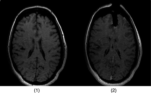
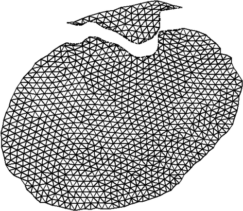
Figure 8. (a) The first iMR image with our estimate of the location of the cut. (b) The mesh created from the brain region of the first iMR image and cut; the cut defines intersections with the mesh.
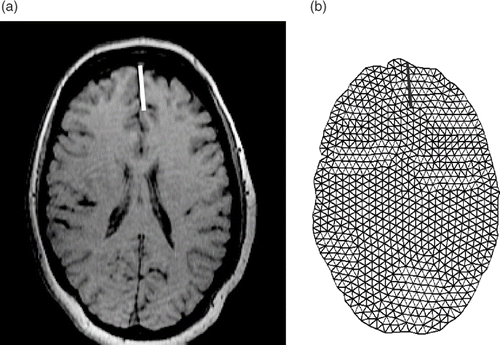
Figure 9. The second iMR image with the cut and, for one particular intersection of the cut with the mesh, the corresponding displacement due to retraction.
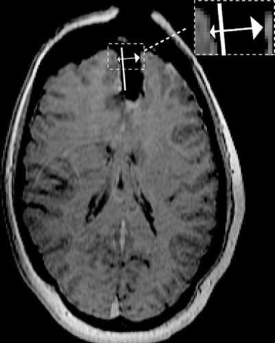
Figure 10. (a) The initial mesh with the cut. (b) The final mesh. The deformation is the result of applying the displacements due to brain shift and retraction to the biomechanical model using XFEM.
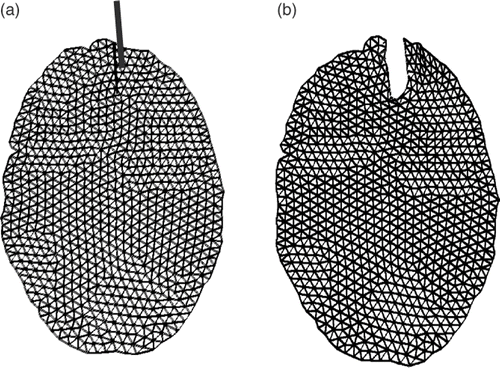
Figure 11. Two-dimensional experimental results for Case 2 (brain shift and retraction). (1a) The first iMR image. (2a) The second iMR image. (1b) Brain extracted from (1a). (2b) Deformation of (1b) using the surface displacement field of the biomechanical model, computed via XFEM. (We say “surface” as we are working in two dimensions.) (1c) Juxtaposition of Canny edges of (1b) and the brain part of (2a). (2c) Juxtaposition of Canny edges of (2b) and the brain part of (2a).
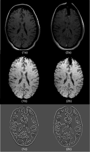
Figure 12. Two-dimensional iMR images for Case 3 (brain shift and successive resections). (1) The first iMR image, acquired before the opening of the skull and dura, and also used as a substitute preoperative image to be updated. (2) The second iMR image, acquired after the opening of the skull and dura, and thus after some brain shift has occurred. (3) The third iMR image, acquired after a first resection. (4) The fourth iMR image, acquired after a second resection. (5) The fifth iMR image, acquired after a third resection and the postoperative brain shift.

Figure 13. Two-dimensional experimental results for modeling of the first resection in Case 3. (1a) The second iMR image. (2a) The third iMR image. (1b) The image resulting from brain-shift modeling [identical to ]. (2b) Deformation of (1b) using the surface displacement field of the biomechanical model, computed via FEM. (We say “surface” as we are working in two dimensions.) (2c) Deformation of (1b) with resection, performed by masking (2b) with the brain region segmented from the third iMR image (2a). (1d) Juxtaposition of Canny edges of (1b) and the brain part of (2a). (2d) Juxtaposition of Canny edges of (2c) and the brain part of (2a).
![Figure 13. Two-dimensional experimental results for modeling of the first resection in Case 3. (1a) The second iMR image. (2a) The third iMR image. (1b) The image resulting from brain-shift modeling [identical to Figure 6(2b)]. (2b) Deformation of (1b) using the surface displacement field of the biomechanical model, computed via FEM. (We say “surface” as we are working in two dimensions.) (2c) Deformation of (1b) with resection, performed by masking (2b) with the brain region segmented from the third iMR image (2a). (1d) Juxtaposition of Canny edges of (1b) and the brain part of (2a). (2d) Juxtaposition of Canny edges of (2c) and the brain part of (2a).](/cms/asset/7ae69f32-1f19-48f1-aef4-eede1f178053/icsu_a_405440_f0013_b.gif)
Figure 14. (a) The final mesh from the modeling of the first resection superimposed on the healthy brain and tumor regions segmented out from the third iMR image. This superimposition allows us to define the tissue discontinuity due to the first resection. (b) Illustration of the XFEM enrichment process for modeling the tissue discontinuity due to the first resection. XFEM Heaviside DOFs are added to each node whose support is intersected by the discontinuity.
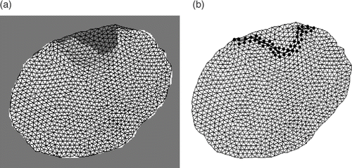
Figure 16. Two-dimensional experimental results for modeling of the second resection in Case 3. (1a) The third iMR image. (2a) The fourth iMR image. (1b) The image resulting from brain shift and first resection modelings, identical to . (2b) Deformation of (1b) using the surface displacement field of the biomechanical model, computed via XFEM. (We say “surface” since we are working in two dimensions.) (1c) The image resulting from brain shift and first resection modelings, identical to . (2c) Deformation of (1b) with resection, performed by masking (2b) with the brain region segmented from the fourth iMR image (2a). (1d) Juxtaposition of Canny edges of (1c) and the brain part of (2a). (2d) Juxtaposition of Canny edges of (2c) and the brain part of (2a).
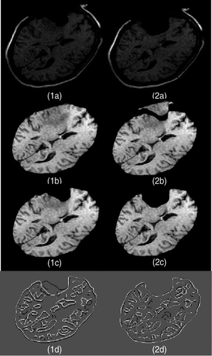
Figure 17. (a) The final mesh resulting from the modeling of the second resection using XFEM, as shown in . (b) The final mesh resulting from the modeling of the second resection using FEM. (c) The reconnected mesh used for modeling the third resection. The positions of the nodes in (c) corresponding to the bottom part of mesh (a) come from mesh (a), while the positions of the nodes corresponding to the top part of mesh (a) come from mesh (b).

Figure 18. Two-dimensional experimental results for modeling of the third resection in Case 3. (1a) The fourth iMR image. (2a) The fifth iMR image. (1b) The image resulting from brain shift, first resection, and second resection modelings, identical to . (2b) Deformation of (1b) using the surface displacement field of the biomechanical model, computed via FEM (using XFEM is also possible). (We say “surface” since we are working in two dimensions.) (1c) The image resulting from brain shift, first resection, and second resection modelings, identical to . (2c) Deformation of (1b) with resection, performed by masking (2b) with the brain region segmented from the fifth iMR image (2a). (1d) Juxtaposition of Canny edges of (1c) and the brain part of (2a). (2d) Juxtaposition of Canny edges of (2c) and the brain part of (2a).
